 |
amxzzw00004279
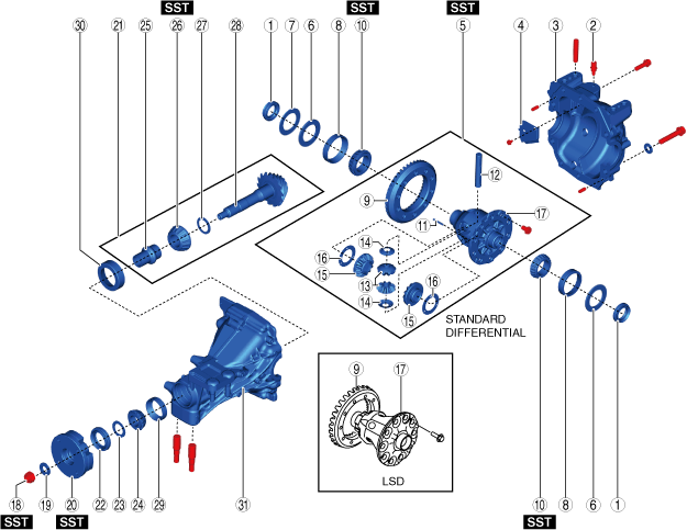
REAR DIFFERENTIAL DISASSEMBLY
id031400800500
1. Disassemble in the order indicated in the table.
amxzzw00004279
|
|
1
|
Oil seal (side gear)
|
|
2
|
Breather
|
|
3
|
Rear cover
(See Rear Cover Disassembly Note.)
|
|
4
|
Baffle plate
|
|
5
|
Differential gear case component
|
|
6
|
Adjustment shim
|
|
7
|
Spacer
|
|
8
|
Side bearing outer race
|
|
9
|
Ring gear
(See Ring Gear Disassembly Note.)
|
|
10
|
Side bearing
|
|
11
|
Spring pin
(See Spring Pin Disassembly Note.)
|
|
12
|
Pinion shaft
|
|
13
|
Pinion gear
|
|
14
|
Washer
|
|
15
|
Side gear
|
|
16
|
Thrust washer
|
|
17
|
Gear case
|
|
18
|
Locknut
(See Locknut Disassembly Note.)
|
|
19
|
Washer
|
|
20
|
Companion flange
|
|
21
|
Drive pinion component
|
|
22
|
Oil seal (companion flange)
|
|
23
|
Spacer
|
|
24
|
Front bearing
|
|
25
|
Collapsible spacer
|
|
26
|
Rear bearing
|
|
27
|
Spacer
|
|
28
|
Drive pinion
|
|
29
|
Front bearing outer race
|
|
30
|
Rear bearing outer race
|
|
31
|
Differential carrier
|
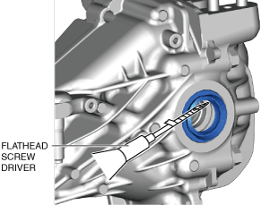
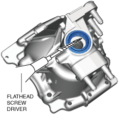
Oil Seal (Side Gear) Disassembly Note
1. Remove the oil seal using a tape-wrapped flathead screwdriver.
amxzzw00004280
|
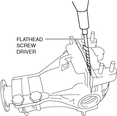
Rear Cover Disassembly Note
1. Remove the rear cover using a tape-wrapped flathead screwdriver.
amxzzw00004281
|
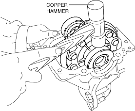
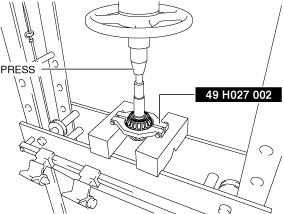
Differential Gear Case Component, Adjustment Shim, Spacer Disassembly Note
1. Lightly tap the side bearing, adjustment shim, and spacer using a copper hammer to place the differential gear case component on the center of the differential carrier.
amxzzw00004282
|
2. Remove the differential gear case component, adjustment shim, and spacer using the SSTs, a press, and a steel plate.
amxzzw00004283
|
Ring Gear Disassembly Note
1. Secure the differential gear case component so that a clearance of approx. 10 mm {0.39 in} has been assured between the ring gear tooth surface and the upper end of the vise as shown in the figure.
amxzzw00004284
|
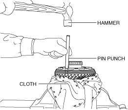
2. Remove the ring gear securing bolts.
3. Protect the ring gear tooth surface using a cloth.
amxzzw00004285
|
4. Remove the ring gear by punching the ring gear in a criss-cross pattern from the bolt installation holes using a pin punch and a hammer.
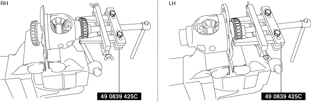
Side Bearing Disassembly Note
1. Remove the side bearing using the SST and a vise.
amxzzw00004286
|
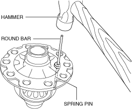
Spring Pin Disassembly Note
1. Tap the spring pin out from the direction shown in the figure using a round bar (diameter: 4 mm {0.2 in}, length: 80 mm {3.1 in}) and a hammer.
amxzzw00004287
|
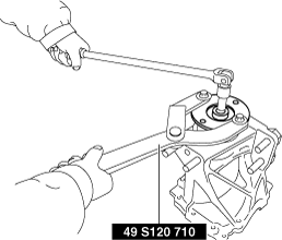
Locknut Disassembly Note
1. Secure the companion flange using the SST and remove the locknut.
amxzzw00004288
|
Companion Flange Disassembly Note
1. Remove the companion flange using the SST and an adjustable wrench.
amxzzw00004289
|
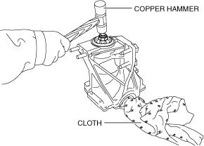
Drive Pinion Component Disassembly Note
1. Install the removed locknut to the drive pinion top to prevent damage to the thread.
amxzzw00004290
|
2. Remove the drive pinion component by tapping the locknut using a copper hammer.
3. Remove the locknut installed in Step 1.
Oil Seal (Companion Flange) Disassembly Note
1. Remove the oil seal using a tape-wrapped flathead screwdriver.
amxzzw00004291
|
Rear Bearing Disassembly Note
1. Remove the rear bearing using the SST and a press.
amxzzw00004292
|
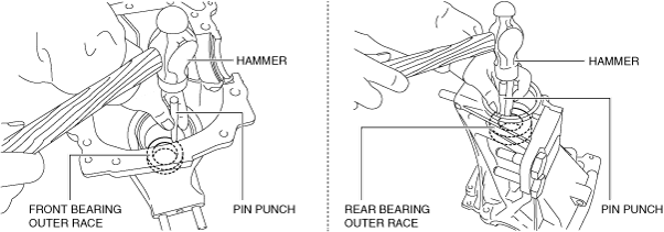
Front Bearing Outer Race, Rear Bearing Outer Race Disassembly Note
1. Remove the bearing outer race by tapping the edge of the bearing outer race using a pin punch and a hammer.
amxzzw00004293
|