 |
amxzzw00004294
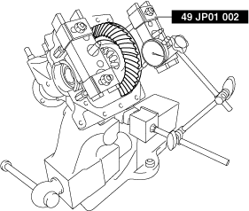
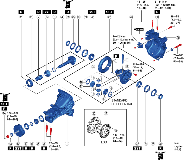
REAR DIFFERENTIAL ASSEMBLY
id031400800600
1. Assemble in the order indicated in the table.
amxzzw00004294
|
|
1
|
Differential carrier
|
|
2
|
Rear bearing outer race
|
|
3
|
Front bearing outer race
|
|
4
|
Drive pinion
|
|
5
|
Spacer
|
|
6
|
Rear bearing
|
|
7
|
Collapsible spacer
|
|
8
|
Front bearing
|
|
9
|
Spacer
|
|
10
|
Oil seal (companion flange)
|
|
11
|
Drive pinion component
|
|
12
|
Companion flange
|
|
13
|
Washer
|
|
14
|
Locknut
|
|
15
|
Differential gear case
|
|
16
|
Thrust washer
|
|
17
|
Side gear
|
|
18
|
Washer
|
|
19
|
Pinion gear
|
|
20
|
Pinion shaft
|
|
21
|
Spring pin
|
|
22
|
Side bearing
(See Side Bearing Assembly Note.)
|
|
23
|
Ring gear
(See Ring Gear Assembly Note.)
|
|
24
|
Side bearing outer race
|
|
25
|
Spacer
|
|
26
|
Adjustment shim
|
|
27
|
Differential gear case component
|
|
28
|
Baffle plate
|
|
29
|
Rear cover
(See Rear Cover Assembly Note.)
|
|
30
|
Breather
|
|
31
|
Oil seal (side gear)
|
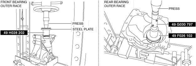
Rear Bearing Outer Race, Front Bearing Outer Race Assembly Note
amxzzw00004295
|
Spacer, Rear Bearing Assembly Note
1. Choose a new spacer with the same thickness as the assembled spacer.
Spacer table
|
Determination mark |
Thickness (mm {in}) |
Determination mark |
Thickness (mm {in}) |
|---|---|---|---|
|
08
|
3.080 {0.1213}
|
29
|
3.290 {0.1295}
|
|
09
|
3.095 {0.1219}
|
30
|
3.305 {0.1301}
|
|
11
|
3.110 {0.1224}
|
32
|
3.320 {0.1307}
|
|
12
|
3.125 {0.1230}
|
33
|
3.335 {0.1313}
|
|
14
|
3.140 {0.1236}
|
35
|
3.350 {0.1319}
|
|
15
|
3.155 {0.1242}
|
36
|
3.365 {0.1325}
|
|
17
|
3.170 {0.1248}
|
38
|
3.380 {0.1331}
|
|
18
|
3.185 {0.1254}
|
39
|
3.395 {0.1337}
|
|
20
|
3.200 {0.1260}
|
41
|
3.410 {0.1343}
|
|
21
|
3.215 {0.1266}
|
42
|
3.425 {0.1348}
|
|
23
|
3.230 {0.1272}
|
44
|
3.440 {0.1354}
|
|
24
|
3.245 {0.1278}
|
45
|
3.455 {0.1360}
|
|
26
|
3.260 {0.1283}
|
47
|
3.470 {0.1366}
|
|
27
|
3.275 {0.1289}
|
—
|
—
|
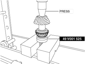
2. Assemble the spacer with the chamfer facing the pinion gear side.
3. Press fit the rear bearing into the drive pinion using the SST and a press.
amxzzw00004296
|
Oil Seal (Companion Flange), Drive Pinion Component, Locknut Assembly Note
1. Adjust the drive pinion preload using the following procedures.
amxzzw00004297
|
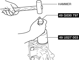
2. Apply differential oil to the lip of a new oil seal.
3. Assemble the oil seal using the SSTs and a hammer.
amxzzw00004298
|
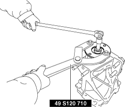
4. Tighten a new locknut and new washer using the SST with the torque recorded at the drive pinion preload adjustment.
amxzzw00004297
|
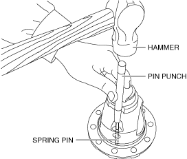
Thrust Washer, Spring Pin Assembly Note
1. Assemble the following parts to the differential gear case.
2. Align the differential gear case and pinion shaft pin holes.
3. Tap the spring pin in using a pin punch and a hammer.
amxzzw00004300
|
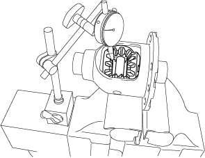
4. Install a dial gauge with the measuring probe of the dial gauge attached perpendicularly to the end of one of the pinion gear teeth.
amxzzw00004301
|
5. Secure one of the side gears.
6. Move the pinion gear and measure the backlash at the pinion gear top.
Thrust Washer table
|
Determination mark |
Thickness (mm {in}) |
|---|---|
|
75
|
0.75 {0.030}
|
|
80
|
0.80 {0.031}
|
|
85
|
0.85 {0.033}
|
|
90
|
0.90 {0.035}
|
|
95
|
0.95 {0.037}
|
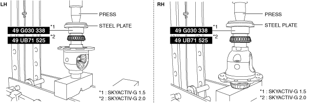
Side Bearing Assembly Note
1. Press fit the side bearing using the SST, a press, and a steel plate.
amxzzw00004302
|
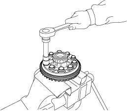
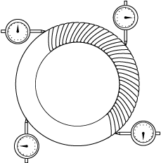
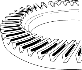
Ring Gear Assembly Note
1. Install the ring gear to the differential gear case and tighten the bolts in a criss-cross pattern.
amxzzw00004303
|
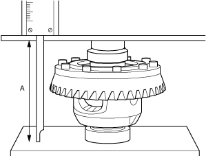
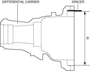
Spacer, Adjustment Shim, Differential Gear Case Component Assembly Note
1. Select the adjustment shim using the following procedure.
amxzzw00004304
|
amxzzw00004305
|
Adjustment shim table
|
Determination mark |
Thickness (mm {in}) |
Determination mark |
Thickness (mm {in}) |
|---|---|---|---|
|
350
|
3.50 {0.138}
|
410
|
4.10 {0.161}
|
|
355
|
3.55 {0.140}
|
415
|
4.15 {0.163}
|
|
360
|
3.60 {0.142}
|
420
|
4.20 {0.165}
|
|
365
|
3.65 {0.144}
|
425
|
4.25 {0.167}
|
|
370
|
3.70 {0.146}
|
430
|
4.30 {0.169}
|
|
375
|
3.75 {0.148}
|
435
|
4.35 {0.171}
|
|
380
|
3.80 {0.150}
|
440
|
4.40 {0.173}
|
|
385
|
3.85 {0.152}
|
445
|
4.45 {0.175}
|
|
390
|
3.90 {0.154}
|
450
|
4.50 {0.177}
|
|
395
|
3.95 {0.156}
|
455
|
4.55 {0.179}
|
|
400
|
4.00 {0.157}
|
460
|
4.60 {0.181}
|
|
405
|
4.05 {0.159}
|
—
|
—
|
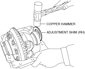
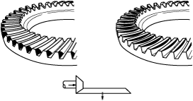
2. Assemble the differential gear case component, side bearing outer race, adjustment shim (LH), and spacer to the differential carrier.
3. Assemble the adjustment shim (RH) between the differential carrier and the side bearing race by tapping it using a copper hammer as shown in the figure.
amxzzw00004306
|
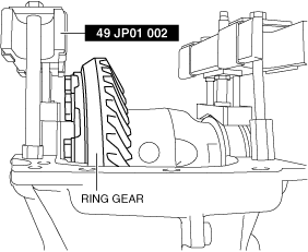
4. Perform the ring gear and drive pinion backlash adjustment.
amxzzw00004307
|
amxzzw00004308
|
amxzzw00004309
|
Adjustment shim table
|
Determination mark |
Thickness (mm {in}) |
Determination mark |
Thickness (mm {in}) |
|---|---|---|---|
|
350
|
3.50 {0.138}
|
410
|
4.10 {0.161}
|
|
355
|
3.55 {0.140}
|
415
|
4.15 {0.163}
|
|
360
|
3.60 {0.142}
|
420
|
4.20 {0.165}
|
|
365
|
3.65 {0.144}
|
425
|
4.25 {0.167}
|
|
370
|
3.70 {0.146}
|
430
|
4.30 {0.169}
|
|
375
|
3.75 {0.148}
|
435
|
4.35 {0.171}
|
|
380
|
3.80 {0.150}
|
440
|
4.40 {0.173}
|
|
385
|
3.85 {0.152}
|
445
|
4.45 {0.175}
|
|
390
|
3.90 {0.154}
|
450
|
4.50 {0.177}
|
|
395
|
3.95 {0.156}
|
455
|
4.55 {0.179}
|
|
400
|
4.00 {0.157}
|
460
|
4.60 {0.181}
|
|
405
|
4.05 {0.159}
|
—
|
—
|
5. Perform the drive pinion and ring gear tooth contact inspection using the following procedure.
amxzzw00004310
|
amxzzw00004371
|
amxzzw00004372
|
Spacer table
|
Determination mark |
Thickness (mm {in}) |
Determination mark |
Thickness (mm {in}) |
|---|---|---|---|
|
08
|
3.080 {0.1213}
|
29
|
3.290 {0.1295}
|
|
09
|
3.095 {0.1219}
|
30
|
3.305 {0.1301}
|
|
11
|
3.110 {0.1224}
|
32
|
3.320 {0.1307}
|
|
12
|
3.125 {0.1230}
|
33
|
3.335 {0.1313}
|
|
14
|
3.140 {0.1236}
|
35
|
3.350 {0.1319}
|
|
15
|
3.155 {0.1242}
|
36
|
3.365 {0.1325}
|
|
17
|
3.170 {0.1248}
|
38
|
3.380 {0.1331}
|
|
18
|
3.185 {0.1254}
|
39
|
3.395 {0.1337}
|
|
20
|
3.200 {0.1260}
|
41
|
3.410 {0.1343}
|
|
21
|
3.215 {0.1266}
|
42
|
3.425 {0.1348}
|
|
23
|
3.230 {0.1272}
|
44
|
3.440 {0.1354}
|
|
24
|
3.245 {0.1278}
|
45
|
3.455 {0.1360}
|
|
26
|
3.260 {0.1283}
|
47
|
3.470 {0.1366}
|
|
27
|
3.275 {0.1289}
|
—
|
—
|
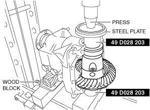
Rear Cover Assembly Note
1. Clean the contact surfaces of the differential carrier and rear cover.
2. Apply pressure to the differential gear case component, adjustment shim, and spacer using the SSTs, a press, and a steel plate.
amxzzw00004313
|
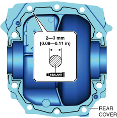
3. Apply silicone sealant (TB1217C) to the positions shown in the figure.
amxzzw00004314
|
4. Install the rear cover to the differential carrier.
Oil Seal (Side Gear) Assembly Note
1. Apply differential oil to the lip of a new oil seal.
2. Assemble the oil seal using the SSTs and a hammer.
amxzzw00004315
|