 |
amxzzn00000727
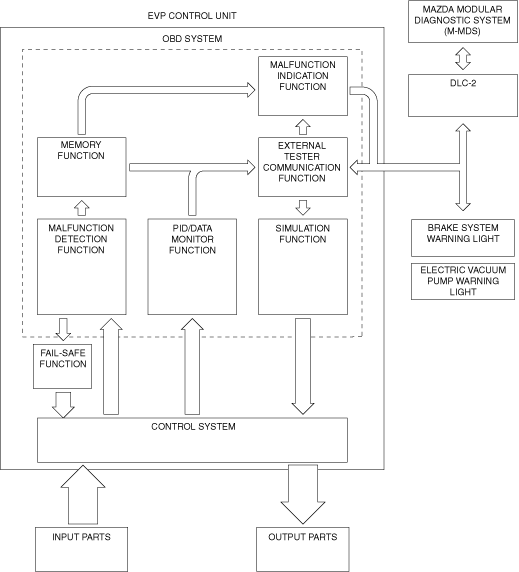
ON-BOARD DIAGNOSTIC SYSTEM [EVP CONTROL UNIT]
id040251836600
Outline
Block diagram
amxzzn00000727
|
Function
Malfunction detection function
Malfunction display function
Memory function
DTC table
|
DTC |
Brake system warning light*1 |
Electric vacuum pump warning light |
Description |
Fail-safe |
Drive cycle |
Self test type*2 |
Memory function |
Priority ranking*4 |
|---|---|---|---|---|---|---|---|---|
|
C101A:00
|
Illuminated
|
Illuminated
|
Vacuum sensor 1/ Vacuum sensor 2 correlation problem
|
×
|
—
|
C, D
|
×
|
6
|
|
C101B:16
|
Not illuminated*3
|
Illuminated
|
Vacuum sensor 1 circuit low input
|
×
|
—
|
C, D
|
×
|
4
|
|
C101B:17
|
Not illuminated*3
|
Illuminated
|
Vacuum sensor 1 circuit high input
|
×
|
—
|
C, D
|
×
|
3
|
|
C101B:1C
|
Not illuminated*3
|
Illuminated
|
Vacuum sensor 1 power supply: low voltage/high voltage
|
×
|
—
|
C, D
|
×
|
2
|
|
C101C:00
|
Illuminated
|
Illuminated
|
Electric vacuum pump: open circuit in drive circuit
|
×
|
—
|
C, D
|
×
|
3
|
|
C101C:18
|
Illuminated
|
Illuminated
|
Electric vacuum pump: drive current decrease
|
×
|
—
|
C, D
|
×
|
4
|
|
C101C:71
|
Illuminated
|
Illuminated
|
Electric vacuum pump: stuck
|
×
|
—
|
C, D
|
×
|
2
|
|
C101C:72
|
Illuminated
|
Illuminated
|
Electric vacuum pump: logic inconsistent
|
×
|
—
|
C, D
|
×
|
6
|
|
C101C:73
|
Illuminated
|
Illuminated
|
Electric vacuum pump: short circuit in drive circuit
|
×
|
—
|
C, D
|
×
|
2
|
|
C1035:11
|
Illuminated
|
Illuminated
|
Electric vacuum pump relay 1: short to ground
|
×
|
—
|
C, D
|
×
|
3
|
|
C1035:12
|
Illuminated
|
Illuminated
|
Electric vacuum pump relay 1: short to power supply
|
×
|
—
|
C, D
|
×
|
2
|
|
C1035:13
|
Illuminated
|
Illuminated
|
Electric vacuum pump relay 1: stuck OFF
|
×
|
—
|
C, D
|
×
|
2
|
|
C1036:11
|
Illuminated
|
Illuminated
|
Electric vacuum pump relay 2: short to ground
|
×
|
—
|
C, D
|
×
|
3
|
|
C1036:12
|
Illuminated
|
Illuminated
|
Electric vacuum pump relay 2: short to power supply
|
×
|
—
|
C, D
|
×
|
2
|
|
C1036:13
|
Illuminated
|
Illuminated
|
Electric vacuum pump relay 2: stuck OFF
|
×
|
—
|
C, D
|
×
|
3
|
|
P050F:00
|
Illuminated
|
Illuminated
|
Low power brake unit vacuum
|
—
|
—
|
C
|
×
|
6
|
|
U0001:88
|
Not illuminated
|
Illuminated
|
CAN communication: module communication error
|
×
|
—
|
C
|
×
|
8
|
|
U0100:00
|
Not illuminated
|
Illuminated
|
CAN communication: communication error to PCM
|
×
|
—
|
C
|
×
|
8
|
|
U0100:08
|
Not illuminated
|
Illuminated
|
CAN communication: communication error to PCM
|
×
|
—
|
C
|
×
|
8
|
|
U0121:00
|
Not illuminated
|
Illuminated
|
CAN communication: communication error to DSC HU/CM
|
—
|
—
|
C
|
×
|
8
|
|
U0121:02
|
Not illuminated
|
Illuminated
|
CAN communication: communication error to DSC HU/CM
|
×
|
—
|
C
|
×
|
8
|
|
U0121:87
|
Not illuminated
|
Illuminated
|
CAN communication: communication error to DSC HU/CM
|
×
|
—
|
C
|
×
|
8
|
|
U0155:00
|
Not illuminated
|
Not illuminated
|
CAN communication: communication error to instrument cluster
|
—
|
—
|
C
|
×
|
8
|
|
U0401:00
|
Not illuminated*3
|
Illuminated
|
CAN communication: signal error from PCM
|
×
|
—
|
C
|
×
|
8
|
|
U0401:86
|
Not illuminated*3
|
Illuminated
|
CAN communication: signal error from PCM
|
×
|
—
|
C
|
×
|
8
|
|
U0415:00
|
Not illuminated
|
Illuminated
|
CAN communication: signal error from DSC HU/CM
|
—
|
—
|
C
|
×
|
8
|
|
U0415:29
|
Not illuminated
|
Illuminated
|
CAN communication: signal error from DSC HU/CM
|
×
|
—
|
C
|
×
|
8
|
|
U0415:86
|
Not illuminated
|
Illuminated
|
CAN communication: signal error from DSC HU/CM
|
×
|
—
|
C
|
×
|
8
|
|
U3000:11
|
Illuminated
|
Illuminated
|
EVP control unit internal circuit malfunction
|
×
|
—
|
C, D
|
×
|
1
|
|
U3000:12
|
Illuminated
|
Illuminated
|
EVP control unit internal circuit malfunction
|
×
|
—
|
C, D
|
×
|
1
|
|
U3000:46
|
Illuminated
|
Illuminated
|
EVP control unit internal circuit malfunction
|
×
|
—
|
C, D
|
×
|
1
|
|
U3000:47
|
Illuminated
|
Illuminated
|
EVP control unit internal circuit malfunction
|
×
|
—
|
C, D
|
×
|
1
|
|
U3000:4B
|
Illuminated
|
Illuminated
|
EVP control unit: high internal temperature
|
×
|
—
|
C, D
|
×
|
6
|
|
U3000:56
|
Illuminated
|
Illuminated
|
EVP control unit internal circuit malfunction
|
×
|
—
|
C, D
|
×
|
1
|
|
U3000:63
|
Illuminated
|
Illuminated
|
EVP control unit: long period of operation
|
×
|
—
|
C
|
×
|
7
|
|
U3000:96
|
Illuminated
|
Illuminated
|
EVP control unit internal circuit malfunction
|
×
|
—
|
C, D
|
×
|
1
|
|
U3003:16
|
Illuminated
|
Illuminated
|
EVP control unit power supply low input
|
×
|
—
|
C
|
×
|
5
|
|
U3003:17
|
Illuminated
|
Illuminated
|
EVP control unit power supply high input
|
×
|
—
|
C
|
×
|
5
|
DTC detection logic and conditions table
|
DTC |
Description |
Detection conditionl |
|---|---|---|
|
C101A:00
|
Vacuum sensor 1/ Vacuum sensor 2 correlation problem
|
• Vacuum sensor 1 and 2 values are compared and the difference is 5 kPa {38 mmHg, 2 inHg} or more for a continuous 1 s.
|
|
C101B:16
|
Vacuum sensor 1 circuit low input
|
• If the EVP control unit detects that the vacuum sensor 1 voltage at the EVP control unit terminal AC is below 0.16 V for 0.6 s, the EVP control unit determines that the vacuum sensor 1 circuit has a malfunction.
|
|
C101B:17
|
Vacuum sensor 1 circuit high input
|
• If the EVP control unit detects that the vacuum sensor 1 voltage at the EVP control unit terminal AC is above 4.9 V for 0.6 s, the EVP control unit determines that the vacuum sensor 1 circuit has a malfunction.
|
|
C101B:1C
|
Vacuum sensor 1 power supply: low voltage/high voltage
|
• Power supply voltage for vacuum sensor 1 deviates from 4.5 V to 5.5 V for a continuous 0.55 s.
|
|
C101C:00
|
Electric vacuum pump: open circuit in drive circuit
|
• An open circuit in the motor drive circuit of the electric vacuum pump occurs for a continuous 0.2 s when the electric vacuum pump is stopped.
|
|
C101C:18
|
Electric vacuum pump: drive current decrease
|
• Electric vacuum pump drive circuit electrical current is low for a continuous 3 s when the electric vacuum pump is operated.
|
|
C101C:71
|
Electric vacuum pump: stuck
|
• Electric vacuum pump drive circuit electrical current is high for a continuous 3 s when the electric vacuum pump is operated.
|
|
C101C:72
|
Electric vacuum pump: logic inconsistent
|
• Control status and the PID value of electric vacuum pump relay 1 or 2 (built into EVP control unit) do not correspond for a continuous 0.2 s.
|
|
C101C:73
|
Electric vacuum pump: short circuit in drive circuit
|
• Resistance of the electric vacuum pump drive circuit is less than 10 m ohm.
|
|
C1035:11
|
Electric vacuum pump relay 1: short to ground
|
• Resistance between the EVP control unit terminal C circuit and ground is less than 10 m ohm.
|
|
C1035:12
|
Electric vacuum pump relay 1: short to power supply
|
• EVP control unit terminal C voltage is 90% or more of the battery voltage for a continuous 0.5 s when electric vacuum pump relay 1 is turned off.
|
|
C1035:13
|
Electric vacuum pump relay 1: stuck OFF
|
• EVP control unit terminal C voltage deviates from the 90% to 110% battery voltage range for a continuous 0.2 s when electric vacuum pump relay 1 is turned on.
|
|
C1036:11
|
Electric vacuum pump relay 2: short to ground
|
• EVP control unit terminal E voltage is less than 1 V for a continuous 0.5 s when electric vacuum pump relay 2 is turned off.
|
|
C1036:12
|
Electric vacuum pump relay 2: short to power supply
|
• EVP control unit terminal E voltage of 2 V or more is detected when the electric vacuum pump is operated.
|
|
C1036:13
|
Electric vacuum pump relay 2: stuck OFF
|
• EVP control unit terminal E voltage is 1 V or more for a continuous 0.2 s when electric vacuum pump relay 2 is turned on.
|
|
P050F:00
|
Low power brake unit vacuum
|
• Power brake unit vacuum is 30 kPa {225 mmHg, 8.8 inHg} lower or more than the barometric pressure for a continuous 15 s when the electric vacuum pump is operating.
|
|
U0001:88
|
CAN communication: module communication error
|
• Open or short circuit in CAN system wiring harness for a continuous 1.4 s.
|
|
U0100:00
|
CAN communication: communication error to PCM
|
• Engine speed signal via CAN communication cannot be received from the PCM for a continuous 5 s.
|
|
U0100:08
|
CAN communication: communication error to PCM
|
• Vacuum sensor 2 signal via CAN communication cannot be received from the PCM for a continuous 5 s.
|
|
U0121:00
|
CAN communication: communication error to DSC HU/CM
|
• CAN communication from the DSC HU/CM is interrupted for a continuous 5 s.
|
|
U0121:02
|
CAN communication: communication error to DSC HU/CM
|
• Brake fluid pressure signal via CAN communication cannot be received from the PCM for a continuous 5 s.
|
|
U0121:87
|
CAN communication: communication error to DSC HU/CM
|
• Vehicle speed signal via CAN communication cannot be received from the DSC HU/CM for a continuous 5 s.
|
|
U0155:00
|
CAN communication: communication error to instrument cluster
|
• CAN communication from the instrument cluster is interrupted for a continuous 5 s.
|
|
U0401:00
|
CAN communication: signal error from PCM
|
• Vacuum sensor 2 signal from the PCM is invalid or not within range for a continuous 1 s.
|
|
U0401:86
|
CAN communication: signal error from PCM
|
• Engine speed signal error from the PCM continues for 5 s.
|
|
U0415:00
|
CAN communication: signal error from DSC HU/CM
|
• Signal from the DSC HU/CM is not received for 5 s.
|
|
U0415:29
|
CAN communication: signal error from DSC HU/CM
|
• Brake fluid pressure error from the DSC HU/CM continues for 1 s.
|
|
U0415:86
|
CAN communication: signal error from DSC HU/CM
|
• Vehicle speed signal error from the DSC HU/CM continues for 5 s.
|
|
U3000:11
|
EVP control unit internal circuit malfunction
|
• Open or short to ground in the temperature sensor circuit inside the EVP control unit continues for 0.1 s.
|
|
U3000:12
|
EVP control unit internal circuit malfunction
|
• Short to power supply in the temperature sensor inside the EVP control unit continues for 0.1 s.
|
|
U3000:46
|
EVP control unit internal circuit malfunction
|
• ROM/RAM data error in the electric vacuum pump is detected.
|
|
U3000:47
|
EVP control unit internal circuit malfunction
|
• Sub CPU/ROM/RAM error in the EVP control unit is detected.
|
|
U3000:4B
|
EVP control unit: high internal temperature
|
• A circuit board temperature inside the EVP control unit of 130 degrees C {266 degrees F} or more is detected.
|
|
U3000:56
|
EVP control unit internal circuit malfunction
|
• ROM/RAM file error in the EVP control unit is detected.
|
|
U3000:63
|
Electric vacuum pump control unit: long period of operation
|
• The electric vacuum pump is used continuously for 180 s or more.
|
|
U3000:96
|
EVP control unit internal circuit malfunction
|
• The A/D converter in the electric vacuum pump unit or the current value of the pump control circuit when the electric vacuum pump is stopped is stuck for a continuous 0.2 s.
|
|
U3003:16
|
EVP control unit power supply low input
|
• The power supply voltage for the EVP control unit is 8.3 V or less for a continuous 0.1 s.
|
|
U3003:17
|
EVP control unit power supply high input
|
• The power supply voltage for the EVP control unit is 17.4 V or more for a continuous 0.1 s.
|
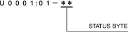
Status byte for DTC
am2zzn00002656
|
Fail-safe function
Fail-safe function table
|
DTC |
Fail-safe function |
|---|---|
|
C101A:00
|
Permits control to drive the motor regularly
|
|
C101B:16
|
Calculates power brake unit vacuum using only vacuum sensor 2 signal, and controls electric vacuum pump
|
|
C101B:17
|
Calculates power brake unit vacuum using only vacuum sensor 2 signal, and controls electric vacuum pump
|
|
C101B:1C
|
Calculates power brake unit vacuum using only vacuum sensor 2 signal, and controls electric vacuum pump
|
|
C101C:00
|
Inhibits electric vacuum pump operation, and DSC HU/CM performs vacuum booster fail support
|
|
C101C:18
|
Inhibits electric vacuum pump operation, and DSC HU/CM performs vacuum booster fail support
|
|
C101C:71
|
Inhibits electric vacuum pump operation, and DSC HU/CM performs vacuum booster fail support
|
|
C101C:72
|
Inhibits electric vacuum pump operation, and DSC HU/CM performs vacuum booster fail support
|
|
C101C:73
|
Inhibits electric vacuum pump operation, and DSC HU/CM performs vacuum booster fail support
|
|
C1035:11
|
Inhibits electric vacuum pump operation, and DSC HU/CM performs vacuum booster fail support
|
|
C1035:12
|
Inhibits electric vacuum pump operation, and DSC HU/CM performs vacuum booster fail support
|
|
C1035:13
|
Inhibits electric vacuum pump operation, and DSC HU/CM performs vacuum booster fail support
|
|
C1036:11
|
Inhibits electric vacuum pump operation, and DSC HU/CM performs vacuum booster fail support
|
|
C1036:12
|
Inhibits electric vacuum pump operation, and DSC HU/CM performs vacuum booster fail support
|
|
C1036:13
|
Inhibits electric vacuum pump operation, and DSC HU/CM performs vacuum booster fail support
|
|
P050F:00
|
—
|
|
U0001:88
|
Inhibits electric vacuum pump operation, and DSC HU/CM performs vacuum booster fail support
|
|
U0100:00
|
Performs control of electric vacuum pump under engine operation condition of engine running
|
|
U0100:08
|
Calculates power brake unit vacuum using only vacuum sensor 1 signal only, and controls electric vacuum pump
|
|
U0121:00
|
—
|
|
U0121:02
|
Controls electric vacuum pump without using brake fluid pressure.
|
|
U0121:87
|
Sets vehicle speed and controls electric vacuum pump.
|
|
U0155:00
|
—
|
|
U0401:00
|
Calculates power brake unit vacuum using only vacuum sensor 1 signal only, and controls electric vacuum pump
|
|
U0401:86
|
Performs control of electric vacuum pump under engine operation condition of engine running
|
|
U0415:00
|
—
|
|
U0415:29
|
Controls electric vacuum pump without using brake fluid pressure.
|
|
U0415:86
|
Sets vehicle speed and controls electric vacuum pump.
|
|
U3000:11
|
Inhibits electric vacuum pump operation, and DSC HU/CM performs vacuum booster fail support
|
|
U3000:12
|
Inhibits electric vacuum pump operation, and DSC HU/CM performs vacuum booster fail support
|
|
U3000:46
|
Inhibits electric vacuum pump operation, and DSC HU/CM performs vacuum booster fail support
|
|
U3000:47
|
Inhibits electric vacuum pump operation, and DSC HU/CM performs vacuum booster fail support
|
|
U3000:4B
|
Inhibits electric vacuum pump operation, and DSC HU/CM performs vacuum booster fail support
|
|
U3000:56
|
Inhibits electric vacuum pump operation, and DSC HU/CM performs vacuum booster fail support
|
|
U3000:63
|
Inhibits electric vacuum pump operation, and DSC HU/CM performs vacuum booster fail support
|
|
U3000:96
|
Inhibits electric vacuum pump operation, and DSC HU/CM performs vacuum booster fail support
|
|
U3003:16
|
Inhibits electric vacuum pump operation, and DSC HU/CM performs vacuum booster fail support
|
|
U3003:17
|
Inhibits electric vacuum pump operation, and DSC HU/CM performs vacuum booster fail support
|
Snapshot data
|
Snapshot data item |
Unit |
Definition |
Data read/use method |
Corresponding data monitor items |
|---|---|---|---|---|
|
AAT
|
°C, °F
|
Ambient air temperature
|
—
|
—
|
|
APP_STATUS
|
Accelerator Pedal Off/
Under 20%/
Over 20%/
FAIL
|
Accelerator pedal position
|
—
|
—
|
|
BRK_SIG
|
Off/On
|
Brake pedal signal
|
—
|
BRK_SIG
|
|
CFG_STATUS
|
Config Complete/
Not Configured/
Config Error
|
Configuration status
|
—
|
—
|
|
ECT_STATUS
|
Under 0 degrees C/
0 - Under 80 degrees C/
Over 80 degrees C/
FAIL
|
Engine coolant temperature status
|
—
|
—
|
|
ECU_TEMP
|
°C, °F
|
ECU internal temperature
|
—
|
ECU_TEMP
|
|
IC_VPWR
|
V
|
Instrument cluster power supply
|
• The EVP control unit constantly receives the power supply voltage value of the instrument cluster sent via CAN signal from the instrument cluster.
• If a DTC is detected, the EVP control unit records the power supply voltage of the instrument cluster when the DTC was detected, and it is displayed in the Mazda Modular Diagnostic System (M-MDS) .
|
—
|
|
IG-ON_TIMER
|
hh:mm:ss*1
|
Elapsed time since ignition was switched ON
|
• The EVP control unit constantly receives the elapsed time since the ignition was switched ON sent via CAN signal from the instrument cluster.
• If a DTC is detected, the EVP control unit records the elapsed time since the ignition was switched ON when the DTC was detected, and it is displayed in the Mazda Modular Diagnostic System (M-MDS) .
|
—
|
|
PWR_MODE_KEY
|
Key Out/Key Recently Out/Key Approved (Position 0)/Post Accessory (Position 0)/Accessory (Position 1)/Post Ignition (Position 1)/Ignition On (Position 2)/Running (Position 2)/Running - Starting In Progress (Position 2)/Crank (Position 3)
|
• Key Out: Ignition switched off
• Key Recently Out (Position 0): Elapsed time within 3 s since ignition was switched off
• Accessory (Position 1): Ignition is switched to ACC
• Post Ignition (Position 2): Elapsed time within 3 s since ignition was switched ON
• Ignition On (Position 2): Ignition switched ON (engine off)
• Running (Position 2): Ignition switched ON (engine on)
• Running - Starting: Cranking condition
|
• The EVP control unit constantly receives the ignition switch status sent via CAN signal from the instrument cluster.
• If a DTC is detected, the EVP control unit records the ignition switch status when the DTC was detected, and it is displayed in the Mazda Modular Diagnostic System (M-MDS) .
|
—
|
|
RPM_STATUS
|
Engine Stop/
Under 1500 rpm/
Over 1500 rpm/
FAIL
|
Engine RPM status
|
• The EVP control unit constantly receives the engine speed sent via CAN signal from the instrument cluster.
• If a DTC is detected, the EVP control unit records the engine speed when the DTC was detected, and it is displayed in the Mazda Modular Diagnostic System (M-MDS) .
|
—
|
|
SHIFT_STATUS
|
P/N
D/
R/
FAIL
|
Shift position status
|
• The EVP control unit constantly receives the selector lever position sent via CAN signal from the instrument cluster.
• If a DTC is detected, the EVP control unit records the selector lever position when the DTC was detected, and it is displayed in the Mazda Modular Diagnostic System (M-MDS) .
|
—
|
|
TOTAL_DIST
|
km, ft, mi
|
Accumulated total traveled distance from completion of vehicle until EVP control unit detects DTC (Odometer value in instrument cluster)
|
The distance traveled when the EVP control unit detected a DTC can be calculated by performing the following procedure.
1. Verify the odometer value in the instrument cluster.
2. Verify the snapshot data item TOTAL_DIST.
3. Subtract 2 from 1.
|
—
|
|
TOTAL_TIME
|
hh:mm:ss*1
|
Accumulated total elapsed time since vehicle completion until EVP control unit detects a DTC
|
The elapsed time when the EVP control unit detected a DTC can be calculated by performing the following procedure.
1. Verify the PID item TOTAL_TIME of the instrument cluster.
2. Verify the snapshot data item TOTAL_TIME.
3. Subtract 2 from 1.
|
—
|
|
VP_C
|
A
|
Electric vacuum pump operation current
|
—
|
VP_C
|
|
VP_MV
|
V
|
Electric vacuum pump terminal voltage (-)
|
—
|
VP_MV
|
|
VP_PV
|
V
|
Electric vacuum pump terminal voltage (+)
|
—
|
VP_PV
|
|
VPD_THR
|
kPa, mmHg, inHg
|
Electric vacuum pump deactivation threshold
• If the power brake unit vacuum is larger than the value which is calculated by subtracting VPD_THR from barometric pressure, the electric vacuum pump is deactivated
|
—
|
VPD_THR
|
|
VPR1_V
|
Off/On
|
Electric vacuum pump relay 1 status
|
—
|
VPR1_V
|
|
VPR2_V
|
Off/On
|
Electric vacuum pump relay 2 status
|
—
|
VPR2_V
|
|
VPS_FBK
|
Off/On
|
Electric vacuum pump status (feedback value)
|
—
|
VPS_FBK
|
|
VPWR
|
V
|
Power supply
|
—
|
VPWR
|
|
VS1
|
kPa, mmHg, inHg
|
Power brake unit vacuum (absolute pressure) detected by vacuum sensor 1
|
—
|
VS1
|
|
VS1_V
|
V
|
Vacuum sensor 1 power supply
|
—
|
VS1_V
|
|
VS2
|
kPa, mmHg, inHg
|
Power brake unit vacuum (absolute pressure) detected by vacuum sensor 2
|
—
|
VS2
|
|
VSPD_STATUS
|
Stop/
0 - 10 km/h/
Over 10 km/h/
FAIL
|
Vehicle speed status
|
• The EVP control unit constantly receives the vehicle speed sent via CAN signal from the instrument cluster.
• If a DTC is detected, the EVP control unit records the vehicle speed when the DTC was detected, and it is displayed in the Mazda Modular Diagnostic System (M-MDS) .
|
—
|
PID/data monitor function
|
Monitor item |
Unit/Operation |
Test condition |
Specification (Reference) |
|---|---|---|---|
|
BRK_SIG
|
Off/On
|
Brake pedal released
|
Off
|
|
Brake pedal depressed
|
On
|
||
|
ECU_TEMP
|
°C, °F
|
This PID indicates temperature of board in EVP control unit.
|
|
|
VP_C
|
A
|
Switch the ignition ON (engine on)
|
approx. 0 A
|
|
After starting to drive
|
approx. 6.5 A
|
||
|
VP_MV
|
V
|
Switch the ignition ON (engine on)
|
approx. 7 V
|
|
After starting to drive
|
approx. 0 V
|
||
|
VP_PV
|
V
|
Switch the ignition ON (engine on)
|
approx. 7 V
|
|
After starting to drive
|
approx. 14 V
|
||
|
VPD_THR
|
—
|
Electric vacuum pump deactivation threshold
• If the power brake unit vacuum is larger than the value which is calculated by subtracting VPD_THR from barometric pressure, the electric vacuum pump is deactivated
|
|
|
VPR1_V
|
Off/On
|
Switch the ignition ON (engine on)
|
Off
|
|
After starting to drive
|
On
|
||
|
VPR2_V
|
Off/On
|
Switch the ignition ON (engine on)
|
Off
|
|
After starting to drive
|
On
|
||
|
VPS_FBK
|
Off/On
|
Switch the ignition ON (engine on)
|
Off
|
|
After starting to drive
|
On
|
||
|
VPWR
|
V
|
This PID indicates power supply voltage for EVP control unit.
|
|
|
VS1
|
Pa, mmHg, inHg
|
Switch the ignition ON (engine on)
|
40 kPa {300 mmHg, 12 inHg} or less
|
|
VS1_INP_STAT
|
—
|
This PID indicates vacuum sensor 1 input status.
|
|
|
VS1_V
|
V
|
Under any condition
|
approx. 5 V
|
|
VS2
|
Pa, mmHg, inHg
|
Switch the ignition ON (engine on)
|
40 kPa {300 mmHg, 12 inHg} or less
|
Simulation function
|
Simulation item |
Operation |
Output part |
Operating condition |
|---|---|---|---|
|
VPS_FBK
|
Off/On
|
Electric vacuum pump
|
For maximum of 30 s when all of the following conditions are met with ignition switched ON (engine off or on)
• Vehicle speed 6 km/h {3 mph} or less
• Operation of electric vacuum pump not inhibited by fail-safe
|
External tester communication function
|
Diagnostic function name |
Signal received |
Signal sent |
|---|---|---|
|
Malfunction detection function
|
DTC verification signal
|
DTC(s)
|
|
PID/data monitor function
|
Command signal to read selected monitor item
|
Monitored data for requested monitor item
|
|
Simulation function
|
Operation command signal for selected simulation item
|
Output part drive signal
|