 |
amxzzw00002841
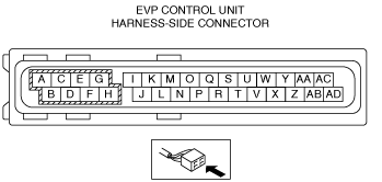
EVP CONTROL UNIT INSPECTION
id041100151900
1. Disconnect the EVP control unit connector. (See EVP CONTROL UNIT REMOVAL/INSTALLATION [L.H.D.].) (See EVP CONTROL UNIT REMOVAL/INSTALLATION [R.H.D.].)
2. Measure the voltage or continuity of the EVP control unit wiring harness-side connector using a tester.
amxzzw00002841
|
Terminal Voltage Table (Reference)
|
Terminal |
Connected to |
Measured item |
Test condition or measured terminal |
Specification (Reference) |
Inspection item |
|---|---|---|---|---|---|
|
A
|
Battery (without i-ELOOP)
|
Voltage
|
Under any condition
|
B+
|
• Inspect the battery.
(See BATTERY INSPECTION.)
• Inspect related wiring harness.
|
|
DC-DC converter (with i-ELOOP)
|
Voltage
|
Under any condition
|
B+
|
• Inspect the DC-DC converter.
• Inspect related wiring harness.
|
|
|
B
|
—
|
—
|
—
|
—
|
—
|
|
C
|
Electric vacuum pump
|
Continuity
|
EVP control unit terminal C—electric vacuum pump terminal B
|
Continuity detected
|
• Inspect the electric vacuum pump.
• Inspect related wiring harness.
|
|
D
|
—
|
—
|
—
|
—
|
—
|
|
E
|
Electric vacuum pump
|
Continuity
|
EVP control unit terminal E—electric vacuum pump terminal A
|
Continuity detected
|
• Inspect the electric vacuum pump.
• Inspect related wiring harness.
|
|
F
|
—
|
—
|
—
|
—
|
—
|
|
G
|
Ground point
|
Continuity
|
EVP control unit terminal G—ground point
|
Continuity detected
|
• Inspect related wiring harness.
|
|
H
|
—
|
—
|
—
|
—
|
—
|
|
I
|
—
|
—
|
—
|
—
|
—
|
|
J
|
—
|
—
|
—
|
—
|
—
|
|
K
|
—
|
—
|
—
|
—
|
—
|
|
L
|
—
|
—
|
—
|
—
|
—
|
|
M
|
—
|
—
|
—
|
—
|
—
|
|
N
|
—
|
—
|
—
|
—
|
—
|
|
O
|
—
|
—
|
—
|
—
|
—
|
|
P
|
IG1 relay
|
Voltage
|
Ignition off
|
1.0 V or less
|
• Inspect the IG1 relay.
(See RELAY INSPECTION.)
• Inspect related wiring harness.
|
|
Ignition ON (engine off)
|
B+
|
||||
|
Q
|
—
|
—
|
—
|
—
|
—
|
|
R
|
—
|
—
|
—
|
—
|
—
|
|
S
|
—
|
—
|
—
|
—
|
—
|
|
T
|
—
|
—
|
—
|
—
|
—
|
|
U
|
—
|
—
|
—
|
—
|
—
|
|
V
|
—
|
—
|
—
|
—
|
—
|
|
W
|
—
|
—
|
—
|
—
|
—
|
|
X
|
—
|
—
|
—
|
—
|
—
|
|
Y
|
Vacuum sensor 1
|
Continuity
|
EVP control unit terminal Y—vacuum sensor 1 terminal B
|
Continuity detected
|
• Inspect the vacuum sensor 1.
(See VACUUM SENSOR 1 INSPECTION.)
• Inspect related wiring harness.
|
|
Z
|
CAN related module
|
Because this terminal is for communication, determination using terminal voltage inspection is not possible. Perform the inspection using the DTC inspection.
|
|||
|
AA
|
Vacuum sensor 1
|
Continuity
|
EVP control unit terminal AA—vacuum sensor 1 terminal A
|
Continuity detected
|
• Inspect the vacuum sensor 1.
(See VACUUM SENSOR 1 INSPECTION.)
• Inspect related wiring harness.
|
|
AB
|
—
|
—
|
—
|
—
|
—
|
|
AC
|
Vacuum sensor 1
|
Continuity
|
EVP control unit terminal AC—vacuum sensor 1 terminal C
|
Continuity detected
|
• Inspect the vacuum sensor 1.
(See VACUUM SENSOR 1 INSPECTION.)
• Inspect related wiring harness.
|
|
AD
|
CAN related module
|
Because this terminal is for communication, determination using terminal voltage inspection is not possible. Perform the inspection using the DTC inspection.
|
|||