 |
amxzzn00001671
TCM
id051300702500
Purpose/Function
Function Table
|
Control item |
Main control content |
|||
|---|---|---|---|---|
|
Shift point control
|
Automatic shift control
(D range)
|
Driving mode
|
Normal mode
|
• Mode selection during normal driving (without drive selection switch)
• Normal mode selected using drive selection (with drive selection switch)
• Performs automatic shift corresponding to vehicle speed and accelerator pedal depression amount
|
|
SPORT mode
(with drive selection switch)
|
• SPORT mode selected using drive selection
• Performs automatic shifting corresponding to vehicle speed and accelerator pedal depression amount
• Lower gear is selected than while in the Normal mode
|
|||
|
Active Adaptive Shift (AAS) mode
|
• Unnecessary shift up is suppressed for several seconds by maintaining the gear corresponding to the operation speed at which the accelerator pedal is released
• The optimum gear on the low vehicle-speed side is selected and shift down is executed corresponding to the operation force at which the brake pedal is depressed
• During cornering, shift up is suppressed in preparation for acceleration after cornering
• In regions of high elevation, the optimum gear is selected corresponding to the environment
• The slope is estimated in the TCM to select the appropriate gear for ascent and descent
• When SPORT mode is selected, the AAS selects a lower gear compared to when normal mode is selected, and maintains it for a longer period of time (with drive selection switch)
|
|||
|
Direct mode control
(D range)
|
• Direct mode control enables temporary use of manual shifting using the steering shift switch even when the selector lever is in the D range
• After switching to direct mode, the system returns to automatic shift mode automatically in accordance with driving conditions
|
|||
|
Manual shift control
(M range)
|
• When M range is selected, manual shifting is prioritized according to the driver’s shift up/shift down operation
|
|||
|
Shift pressure control
|
Line pressure control
|
• Controls line pressure with high accuracy and fine control corresponding to engine load conditions and vehicle driving conditions
|
||
|
Learning control
|
• Learns engine performance changes and transmission deterioration over time to optimally correct clutch engagement pressure
|
|||
|
Torque converter clutch (TCC) control, slip control
|
• By gradually engaging/disengaging TCC piston, shock during operation is reduced
• Implements TCC control when accelerator pedal is fully closed for improved fuel economy and emission performance
• Slip control, by sliding the TCC when TCC is in the off range, extends the TCC range to low vehicle speeds.
|
|||
|
i-stop control
|
• When i-stop (engine-stop control) permit conditions are met and engine is stopped, TCM sends electric AT oil pump drive signal to the electric AT oil pump driver control unit
• Monitors the condition of the electric AT oil pump according to the electric AT oil pump operating condition signal from electric AT oil pump driver control unit
|
|||
|
Engine-transmission integration control
|
• Optimally controls engine output torque when shifting
• Calculates optimum clutch engagement pressure according to engine output torque
|
|||
|
On-board diagnostic system
|
• Main part of transmission control includes self-diagnosis function. In case of malfunction, automatic transmission warning light illuminates to alert driver, and DTC is stored in TCM
• When transmission malfunction is determined resulting from on-board diagnostic test, system control is switched to prevent any dangerous situation while driving
|
|||
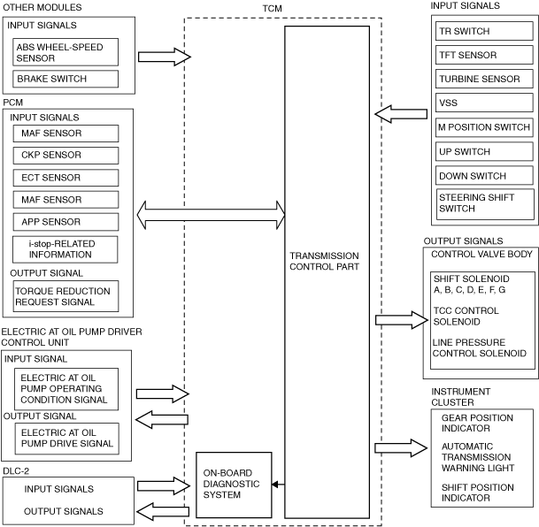
Construction
Block diagram
amxzzn00001671
|
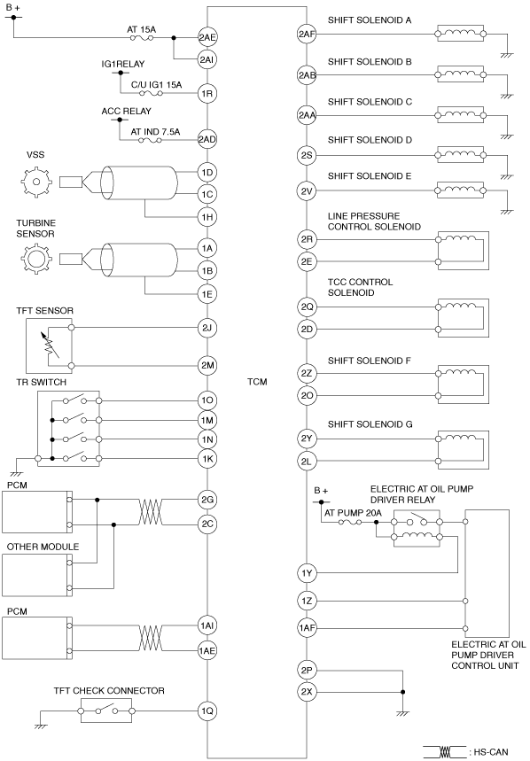
System wiring diagram
amxzzw00004232
|
Operation
Input/Output signal and related controls
|
Component |
Control |
||||||||||||
|---|---|---|---|---|---|---|---|---|---|---|---|---|---|
|
Automatic shift control (D position) |
Direct mode control (D range) |
Manual shift control (M position) |
Neutral control |
Reverse control |
Line pressure control |
Learning control |
Torque converter clutch (TCC) control, slip control |
Engine-transmission integration control |
i-stop control |
On-board diagnostic system |
|||
|
Input
|
VSS
|
X
|
X
|
X
|
X
|
X
|
X
|
|
X
|
|
X
|
X
|
|
|
Turbine sensor
|
X
|
|
X
|
X
|
X
|
X
|
X
|
X
|
X
|
|
X
|
||
|
TR switch
|
X
|
X
|
X
|
X
|
X
|
|
|
|
|
X
|
|
||
|
TFT sensor
|
X
|
|
X
|
|
X
|
|
X
|
|
X
|
|
|||
|
CAN
|
M position switch
|
|
|
X
|
|
X
|
|
|
|
|
|
||
|
Up switch
|
|
|
X
|
|
X
|
|
|
|
|
|
|||
|
Down switch
|
|
|
X
|
|
X
|
|
|
|
|
|
|||
|
Steering shift switch
|
|
X
|
X
|
|
X
|
|
|
|
|
|
|||
|
Brake switch
|
|
|
|
|
|
|
X
|
|
X
|
|
|||
|
Throttle opening signal (APP sensor)
|
X
|
X
|
X
|
X
|
|
X
|
|
|
X
|
|
|||
|
Engine speed signal (Eccentric shaft position sensor)
|
|
X
|
|
|
X
|
X
|
X
|
X
|
X
|
||||
|
Engine torque signal (MAF sensor)
|
|
|
|
|
X
|
X
|
|
X
|
X
|
||||
|
Engine coolant temperature signal (ECT sensor)
|
X
|
|
|
|
|
|
X
|
|
X
|
||||
|
Drive selection signal
|
X
|
|
|
|
|
|
|
|
X
|
||||
|
Wheel speed signal (wheel speed sensor)
|
X
|
X
|
|
X
|
|
|
|
|
|
|
|||
|
Output
|
ON/OFF type
|
Shift solenoid A
|
X
|
X
|
X
|
|
X
|
|
|
X
|
|||
|
Shift solenoid B
|
X
|
X
|
X
|
X
|
|
X
|
|
|
X
|
||||
|
Shift solenoid C
|
X
|
X
|
X
|
X
|
|
X
|
|
|
X
|
||||
|
Shift solenoid D
|
X
|
X
|
X
|
|
X
|
|
|
X
|
|||||
|
Shift solenoid E
|
X
|
X
|
X
|
X
|
X
|
|
X
|
|
|
X
|
|||
|
Linear type
|
Line pressure control solenoid
|
X
|
X
|
X
|
X
|
X
|
|
|
X
|
||||
|
TCC control solenoid
|
|
|
|
|
|
X
|
|
X
|
|||||
|
Shift solenoid F
|
X
|
X
|
X
|
X
|
X
|
X
|
|
|
X
|
||||
|
Shift solenoid G
|
X
|
X
|
X
|
X
|
X
|
X
|
|
|
X
|
||||
|
CAN
|
AT warning light
|
X
|
|
X
|
|
|
|
|
X
|
||||
|
Torque reduction request signal
|
|
|
|
|
|
|
X
|
|
|
||||
|
Speedometer signal
|
|
|
|
|
|
|
|
|
|
||||
|
Electric AT oil pump driver control unit
|
|
|
|
|
|
|
|
X
|
|
||||