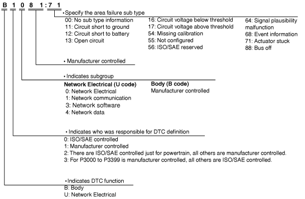
 |
ac5uun00000518
ON-BOARD DIAGNOSTIC
id070200126600
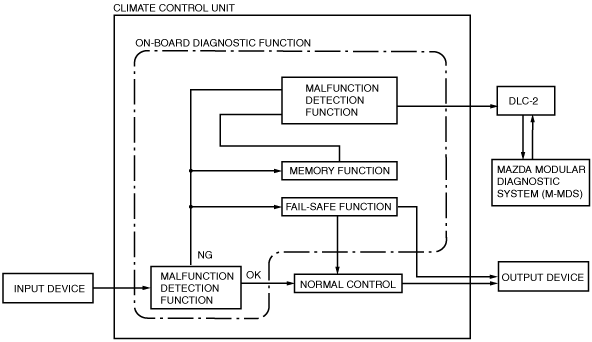
Outline
Block Diagram
ac5uun00000518
|
Function
Malfunction detection function
Memory function
Malfunction indication function
Full-auto air conditioner
|
DTC No. |
Warning/indicator light |
System malfunction location |
Fail-safe function |
Drive cycle |
Self test type*1 |
Memory function |
|---|---|---|---|---|---|---|
|
B1086:71
|
—
|
Airflow mode actuator motor lock
|
X
|
—
|
C
|
X
|
|
B10BE:12
|
—
|
Solar radiation sensor circuit short to power supply
|
X
|
—
|
C,D
|
X
|
|
B10BE:13
|
—
|
Solar radiation sensor circuit open
|
X
|
—
|
D
|
X
|
|
B13AA:71
|
—
|
Air mix actuator motor lock
|
X
|
—
|
C
|
X
|
|
B13AB:12
|
—
|
Air mix actuator (potentiometer) circuit short to power supply
|
X
|
—
|
C, D
|
X
|
|
B13AB:13
|
—
|
Air mix actuator (potentiometer) circuit open
|
X
|
—
|
C, D
|
X
|
|
B1A61:11
|
—
|
Cabin temperature sensor circuit short to ground
|
X
|
—
|
C, D
|
X
|
|
B1A61:13
|
—
|
Cabin temperature sensor circuit open
|
X
|
—
|
C, D
|
X
|
|
B1B71:11
|
—
|
Evaporator temperature sensor circuit short to ground
|
X
|
—
|
C, D
|
X
|
|
B1B71:13
|
—
|
Evaporator temperature sensor circuit open
|
X
|
—
|
C, D
|
X
|
|
B1C1C:12
|
—
|
Airflow mode actuator (potentiometer) circuit short to power supply
|
X
|
—
|
C, D
|
X
|
|
B1C1C:13
|
—
|
Airflow mode actuator (potentiometer) circuit open
|
X
|
—
|
C, D
|
X
|
|
U0010:88
|
—
|
Unit communication error (MS-CAN)
|
X
|
—
|
C
|
X
|
|
U0155:00
|
—
|
Communication error with instrument cluster
|
X
|
—
|
C, D
|
X
|
|
U0423:68
|
—
|
Invalid data received from Instrument cluster
|
X
|
—
|
C, D
|
X
|
|
U200D:11
|
—
|
Climate control unit circuit voltage (+5V) circuit short to ground
|
—
|
—
|
C, D
|
X
|
|
U2300:54
|
—
|
Configuration error (data not received)
|
X
|
—
|
C, D
|
X
|
|
U2300:55
|
—
|
Configuration error (not configured)
|
X
|
—
|
C, D
|
—
|
|
U2300:56
|
—
|
Configuration error (ineffective/non-interchangeable data read)
|
X
|
—
|
C, D
|
X
|
|
U2300:64
|
—
|
Configuration error (error value read)
|
X
|
—
|
C, D
|
X
|
|
U3003:16
|
—
|
Climate control unit power supply circuit voltage below threshold (10 V or less)
|
—
|
—
|
C, D
|
X
|
|
U3003:17
|
—
|
Climate control unit power supply circuit voltage above threshold (17.3 V or more)
|
—
|
—
|
C, D
|
X
|
|
U300E:13
|
—
|
Climate control unit power supply circuit open (IG1)
|
—
|
—
|
C, D
|
X
|
Manual air conditioner
|
DTC No. |
Warning/indicator light |
System malfunction location |
Fail-safe function |
Drive cycle |
Self test type*1 |
Memory function |
|---|---|---|---|---|---|---|
|
B1086:71
|
—
|
Airflow mode actuator motor lock
|
X
|
—
|
C
|
X
|
|
B13AA:71
|
—
|
Air mix actuator motor lock
|
X
|
—
|
C
|
X
|
|
B13AB:12
|
—
|
Air mix actuator (potentiometer) circuit short to power supply
|
X
|
—
|
C, D
|
X
|
|
B13AB:13
|
—
|
Air mix actuator (potentiometer) circuit open
|
X
|
—
|
C, D
|
X
|
|
B1B71:11
|
—
|
Evaporator temperature sensor circuit short to ground
|
X
|
—
|
C, D
|
X
|
|
B1B71:13
|
—
|
Evaporator temperature sensor circuit open
|
X
|
—
|
C, D
|
X
|
|
B1C1C:12
|
—
|
Airflow mode actuator (potentiometer) circuit short to power supply
|
X
|
—
|
C, D
|
X
|
|
B1C1C:13
|
—
|
Airflow mode actuator (potentiometer) circuit open
|
X
|
—
|
C, D
|
X
|
|
U0010:88
|
—
|
Unit communication error (MS-CAN)
|
X
|
—
|
C
|
X
|
|
U0155:00
|
—
|
Communication error with instrument cluster
|
X
|
—
|
C, D
|
X
|
|
U0423:68
|
—
|
Invalid data received from Instrument cluster
|
X
|
—
|
C, D
|
X
|
|
U200D:11
|
—
|
Climate control unit circuit voltage (+5V) circuit short to ground
|
—
|
—
|
C, D
|
X
|
|
U2300:54
|
—
|
Configuration error (data not received)
|
X
|
—
|
C, D
|
X
|
|
U2300:55
|
—
|
Configuration error (not configured)
|
X
|
—
|
C, D
|
—
|
|
U2300:56
|
—
|
Configuration error (ineffective/non-interchangeable data read)
|
X
|
—
|
C, D
|
X
|
|
U2300:64
|
—
|
Configuration error (error value read)
|
X
|
—
|
C, D
|
X
|
|
U3003:16
|
—
|
Climate control unit power supply circuit voltage below threshold (10 V or less)
|
—
|
—
|
C, D
|
X
|
|
U3003:17
|
—
|
Climate control unit power supply circuit voltage above threshold (17.3 V or more)
|
—
|
—
|
C, D
|
X
|
|
U300E:13
|
—
|
Climate control unit power supply circuit open (IG1)
|
—
|
—
|
C, D
|
X
|
ac5wzn00001320
|
ac5wzn00001326
|
PID/data monitor
PID/data monitor table
Full-auto air conditioner
|
PID |
Unit/Condition |
Data contents |
Climate control unit terminal |
|---|---|---|---|
|
A/C_SW
|
Off/On
|
• Off: A/C switch is off.
• On: A/C switch is on.
|
—
|
|
B_MT_RLY_CS
|
Off/On
|
• Off: Blower relay is off.
• On: Blower relay is on.
|
B, D (CAN)
|
|
ELE_W/P
|
|
||
|
ENG_C_TMP
|
°C, °F
|
Engine coolant temperature is displayed.
|
B, D (CAN)
|
|
EVA_TMP_SEN
|
°C, °F
|
Evaporator temperature is displayed.
|
J, E
|
|
F_REC_CS
|
Off/On
|
• Off: Forced recirculate control is off.
• On: Forced recirculate control is on.
|
—
|
|
INC_TMP_SEN
|
°C, °F
|
Cabin temperature is displayed.
|
E, F
|
|
OUT_CAR_TMP
|
°C, °F
|
Ambient temperature is displayed.
|
—
|
|
R/DEF_CS
|
Off (enable)/
Off (suspend)/
Off (inhibit)/
On
|
• Off (enable): Rear window defogger is off (operation enabled).
• Off (suspend): Rear window defogger is off (operation interrupted / indicator is kept On).
• Off (inhibit): Rear window defogger is off (operation disabled / indicator is turned Off).
• On: Rear window defogger is on.
|
—
|
|
R/DEF_SW
|
Off/On
|
• Off: Rear window defogger switch is off.
• On: Rear window defogger switch is on.
|
—
|
|
REC_SW
|
Off/On
|
• Off: RECIRCULATE switch is off.
• On: RECIRCULATE switch is on.
|
—
|
|
SLR_R_SEN
|
W/m2
|
Solar radiation amount is displayed.
|
K
|
|
STOP_ST
|
Available/
Not Available/
Error
|
• Available: i-stop permit request signal is sent.
• Not Available: i-stop inhibit request is sent.
• Error: i-stop signal error is sent.
|
B, D (CAN)
|
Manual air conditioner
|
PID |
Unit/Condition |
Data contents |
Climate control unit terminal |
|---|---|---|---|
|
A/C_SW
|
Off/On
|
• Off: A/C switch is off.
• On: A/C switch is on.
|
—
|
|
B_MT_RLY_CS
|
Off/On
|
• Off: Blower relay is off.
• On: Blower relay is on.
|
B, D (CAN)
|
|
ELE_W/P
|
|
||
|
ENG_C_TMP
|
°C, °F
|
Engine coolant temperature is displayed.
|
B, D (CAN)
|
|
EVA_TMP_SEN
|
°C, °F
|
Evaporator temperature is displayed.
|
J
|
|
F_REC_CS
|
Off/On
|
• Off: Forced recirculate control is off.
• On: Forced recirculate control is on.
|
—
|
|
OUT_CAR_TMP
|
°C, °F
|
Ambient temperature is displayed.
|
—
|
|
R/DEF_CS
|
Off (enable)/
Off (suspend)/
Off (inhibit)/
On
|
• Off (enable): Rear window defogger is off (operation enabled).
• Off (suspend): Rear window defogger is off (operation interrupted / indicator is kept On).
• Off (inhibit): Rear window defogger is off (operation disabled / indicator is turned Off).
• On: Rear window defogger is on.
|
—
|
|
R/DEF_SW
|
Off/On
|
• Off: Rear window defogger switch is off.
• On: Rear window defogger switch is on.
|
—
|
|
REC_SW
|
Off/On
|
• Off: RECIRCULATE switch is off.
• On: RECIRCULATE switch is on.
|
—
|
|
SLR_R_SEN
|
|
||
|
STOP_ST
|
Available/
Not Available/
Error
|
• Available: i-stop permit request signal is sent.
• Not Available: i-stop inhibit request is sent.
• Error: i-stop signal error is sent.
|
B, D (CAN)
|
A/C operation check mode
|
Mazda Modular Diagnostic System (M-MDS) display |
Target part |
Reference |
|---|---|---|
|
Air Mix Actuator
|
Air mix actuator
Air mix door
|
(See Air mix actuator.)
|
|
Air conditioning compressor
|
A/C compressor
|
(See A/C compressor.)
|
|
Air Intake Actuator
|
Air intake actuator
Air intake door
|
(See Air intake actuator.)
|
|
Blower Motor Speed
|
Blower motor
|
(See Blower motor .)
|
|
Airflow Mode Actuator
|
Airflow mode actuator
Airflow mode door
|
(See Airflow mode actuator.)
|
|
Illumination Of All Indicator Lights
|
Climate control unit
|
(See Indicator light.)
|
Air mix actuator
Operation
|
Step |
Air mix actuator |
Airflow mode actuator |
Blower speed |
Magnet clutch |
Air intake actuator |
|---|---|---|---|---|---|
|
1
|
0 %
|
VENT
|
5th
|
ON
|
FRESH
|
|
2
|
100 %
|
Indicator light
|
Step |
Recirculate switch indicator light |
Rear window defogger switch indicator light |
A/C switch indicator light |
|---|---|---|---|
|
1
|
Not Illuminated
|
Not illuminated
|
Illuminated
|
|
2
|
A/C compressor
Operation
|
Step |
Air mix actuator |
Airflow mode actuator |
Blower speed |
Magnet clutch |
Air intake actuator |
|---|---|---|---|---|---|
|
1
|
0 %
|
VENT
|
5th
|
ON
|
FRESH
|
|
2
|
OFF
|
Indicator light
|
Step |
Recirculate switch indicator light |
Rear window defogger switch indicator light |
A/C switch indicator light |
|---|---|---|---|
|
1
|
Not illuminated
|
Not illuminated
|
Illuminated
|
|
2
|
Not illuminated
|
Air intake actuator
Operation
|
Step |
Air mix actuator |
Airflow mode actuator |
Blower speed |
Magnet clutch |
Air intake actuator |
|---|---|---|---|---|---|
|
1
|
0 %
|
VENT
|
5th
|
ON
|
FRESH
|
|
2
|
RECIRCULATE
|
||||
|
3
|
OFF
|
FRESH
|
|||
|
4
|
RECIRCULATE
|
Indicator light
|
Step |
Recirculate switch indicator light |
Rear window defogger switch indicator light |
A/C switch indicator light |
|---|---|---|---|
|
1
|
Not illuminated
|
Not illuminated
|
Illuminated
|
|
2
|
Illuminated
|
||
|
3
|
Not illuminated
|
Not illuminated
|
|
|
4
|
Illuminated
|
Blower motor
Operation
|
Step |
Air mix actuator |
Airflow mode actuator |
Blower speed |
Magnet clutch |
Air intake actuator |
|---|---|---|---|---|---|
|
1
|
50 %
|
VENT
|
OFF
|
OFF
|
FRESH
|
|
2
|
1st
|
ON
|
|||
|
3
|
3rd
|
||||
|
4
|
5th
|
||||
|
5
|
7th
|
Indicator light
|
Step |
Recirculate switch indicator light |
Rear window defogger switch indicator light |
A/C switch indicator light |
|---|---|---|---|
|
1
|
Not illuminated
|
Not illuminated
|
Not illuminated
|
|
2
|
Illuminated
|
||
|
3
|
|||
|
4
|
|||
|
5
|
Airflow mode actuator
Operation
|
Step |
Air mix actuator |
Airflow mode actuator |
Blower speed |
Magnet clutch |
Air intake actuator |
|---|---|---|---|---|---|
|
1
|
50 %
|
VENT
|
5th
|
ON
|
FRESH
|
|
2
|
BI-LEVEL
|
||||
|
3
|
HEAT
|
||||
|
4
|
DEF/HEAT
|
||||
|
5
|
DEFROSTER
|
Indicator light
|
Step |
Recirculate switch indicator light |
Rear window defogger switch indicator light |
A/C switch indicator light |
|---|---|---|---|
|
1
|
Not illuminated
|
Not illuminated
|
Illuminated
|
|
2
|
|||
|
3
|
|||
|
4
|
|||
|
5
|
Indicator light
Operation
|
Step |
Air mix actuator |
Airflow mode actuator |
Blower speed |
Magnet clutch |
Air intake actuator |
|---|---|---|---|---|---|
|
—
|
50 %
|
VENT
|
OFF
|
OFF
|
FRESH
|
Indicator light
|
Step |
Recirculate switch indicator light |
Rear window defogger switch indicator light |
A/C switch indicator light |
|---|---|---|---|
|
—
|
Illuminated
|
Illuminated
|
Illuminated
|
A/C operation check stop
Operation
|
Step |
Air mix actuator |
Airflow mode actuator |
Blower speed |
Magnet clutch |
Air intake actuator |
|---|---|---|---|---|---|
|
—
|
50 %
|
VENT
|
OFF
|
OFF
|
FRESH
|
Indicator light
|
Step |
Recirculate switch indicator light |
Rear window defogger switch indicator light |
A/C switch indicator light |
|---|---|---|---|
|
—
|
Not illuminated
|
Not illuminated
|
Not illuminated
|