REFRIGERANT CHARGING
id071000300100
-
Caution
-
• Do not use a different type of refrigerant or charge beyond the specified level. Otherwise, cooling ability will be lowered and the refrigerant system parts could be damaged.
-
Note
-
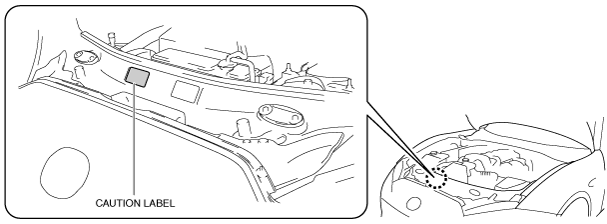
• The refrigerant used for the refrigerant system differs depending on the country. When draining or adding the refrigerant, verify the appropriate refrigerant type and specified amount of refrigerant from the caution label.
-
Refrigerant type
-
HFC-134a (R-134a)
HFO-1234yf (R-1234yf)
-
Regular amount of refrigerant (approx. quantity)
-
395—445 g{14.0—15.6 oz} (HFC-134a)
335—385 g{11.9—13.5 oz} (HFO-1234yf)
Charging Recycled Refrigerant
1. Correctly collect the refrigerant following the instructions for the chlorofluorocarbon (CFC) recovery machine being used.
Adding Compressor Oil
1. Weigh the compressor oil which is exhausted when collecting the refrigerant.
2. When adding refrigerant, add new compressor oil equivalent in weight to the exhausted amount to the refrigerant cycle.
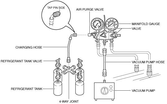
Charging Preparation
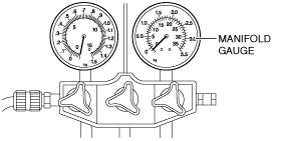
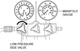
1. Close all the valves of the manifold gauge.
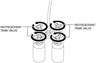
2. Close all the refrigerant tank valves.
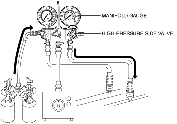
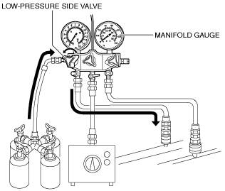
3. Install the manifold gauge set. (See MANIFOLD GAUGE SET CONNECTION.)
4. Connect the vacuum pump hose to the manifold gauge.
5. Connect the tap pin side of the charging hose to the air purge valve of the manifold gauge.
6. Install the refrigerant tank valves to the 4-way joint.
7. Install the 4-way joint to the charging hose (no-tap pin side).
8. Install the refrigerant tanks with the specified amount of refrigerant to the refrigerant tank valves.
9. Connect the vacuum pump hose to the vacuum pump.
10. Perform an evacuation. (See Evacuation.)
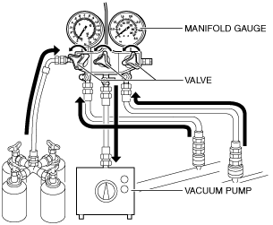
Evacuation
1. Open all the valves of the manifold gauge.
2. Start the vacuum pump and let it operate for 15 min.
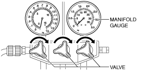
3. Verify that high- and low-pressure side readings of the manifold gauge are at -0.1 MPa {-1 kgf/cm2, -15 psi}.
4. Stop the vacuum pump.
-
Caution
-
• If the manifold gauge valves are left open, vacuum pump oil will backflow into the refrigeration cycle and cause the cooling performance to lower. After stopping the vacuum pump, close the manifold gauge valves immediately.
5. Close all the valves of the manifold gauge.
6. Wait for 5 min after stopping the vacuum pump, and perform an airtightness check for the refrigerant system. (See Airtightness Check.)
Airtightness Check
1. Verify that the manifold gauge reading has not changed.
-
• If the manifold gauge reading has changed, inspect the refrigerant system following the symptom troubleshooting procedure. (See
FOREWORD [CLIMATE CONTROL SYSTEM].)
Charging New Refrigerant
-
Warning
-
• If the refrigerant system is charged with a large amount of refrigerant when inspecting for gas leakage, and if any leakage should occur, the refrigerant will be released into the atmosphere. In order to prevent the accidental release of refrigerant which can destroy the ozone layer in the stratosphere, follow the proper procedures and charge with only a small amount of refrigerant when inspecting for gas leakage.
-
Caution
-
• If charging of refrigerant is started from the low pressure side, the A/C compressor vanes will not expand outward and an abnormal sound may be heard. Always start the refrigerant charging from the high pressure side.
1. Open the refrigerant tank valves.
-
Warning
-
• Never start the engine while the valve on the high pressure side is open. If the engine is started while the manifold gauge valve on the high pressure side is open, highly pressurized refrigerant could backflow into the refrigerant tanks and cause damage.
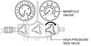
2. Open the high-pressure side valve of the manifold gauge.
3. Verify that low-pressure side readings of the manifold gauge is at 0.1 MPa {1 kgf/cm2, 15 psi}.
4. Close the high-pressure side valve of the manifold gauge.
5. Inspect for gas leakage from the piping connection using a gas leak detector or a fluorescent agent-detecting UV black light.
-
• If there is no leakage, go to Step 7.
• If leakage is found at a loose joint, tighten the joint, then go to next step.
6. Inspect for leakage again.
-
• If there is no leakage after tightening the joint, go to next step.
-
Warning
-
• Never start the engine while the valve on the high pressure side is open. If the engine is started while the manifold gauge valve on the high pressure side is open, highly pressurized refrigerant could backflow into the refrigerant tanks and cause damage.
7. Open the high-pressure side valve of the manifold gauge.
-
Caution
-
• Never charge refrigerant with the refrigerant tanks upside down. If the refrigerant system is charged with the refrigerant tanks upside down, liquid refrigerant will be charged into the system, and the A/C compressor could become highly pressurized and damaged.
8. Charge with approx. 1/2 of the specified amount of refrigerant.
9. Close the high-pressure side valve of the manifold gauge.
10. Start the engine and actuate the A/C compressor.
11. Open the low-pressure side valve of the manifold gauge.
-
Caution
-
• Never charge refrigerant with the refrigerant tanks upside down. If the refrigerant system is charged with the refrigerant tanks upside down, liquid refrigerant will be charged into the system, and the A/C compressor could become highly pressurized and damaged.
12. Charge the remaining refrigerant (approx. 1/2 of amount of specified refrigerant).
13. Close the low-pressure side valve of the manifold gauge.
14. Stop the engine.
15. Perform the leak test. (See Leak Test.)
Leak Test
-
Caution
-
• Looking directly at a fluorescent agent-detecting UV black light may cause injury to the eyes. Do not look directly into the light of a fluorescent agent-detecting UV black light.
-
Note
-
• Because fluorescent agents (yellow or light green dye) are in the refrigeration cycle, the leak test can be performed with a fluorescent agent-detecting UV black light.
1. Inspect for gas leakage from the piping connection using a gas leak detector or a fluorescent agent-detecting UV black light.
-
• If there is no leakage, go to Step 3.
• If leakage is found at a loose joint, tighten the joint, then go to the next step.
2. Inspect for leakage again.
-
• If there is no refrigerant leakage, perform the procedure from the evacuation again. (See
Evacuation.)
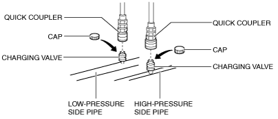
3. Disconnect the quick couplers from the charging valves.
4. Install the caps to the charging valves.