FULL-AUTO AIR CONDITIONER SYSTEM [FULL-AUTO AIR CONDITIONER]
id0740a1004000
Outline
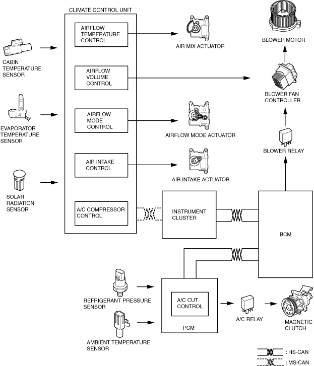
• The climate control unit performs the following controls based on the signals from each switch/dial and the sensor.
-
― Airflow temperature control
― Airflow volume control
― Airflow mode control
― Air intake control
― A/C compressor control
― Air conditioner i-stop control (With i-stop)
Function
Airflow temperature control
-
• The airflow temperature control operates the air mix actuator and switches the air mix damper position in conjunction with the airflow temperature setting and the vehicle conditions.
Airflow volume control
-
• The airflow volume control changes the blower motor control speed and switches the airflow volume in conjunction with the airflow volume setting and the vehicle conditions.
Airflow mode control
-
• The airflow mode control operates the airflow mode actuator and switches the airflow mode door position in conjunction with the airflow mode setting and the vehicle conditions.
Air intake control
-
• The air intake control operates the air intake actuator and switches the air intake door position in conjunction with the air intake setting and the vehicle conditions.
A/C compressor control
-
• The A/C compressor control sends the A/C signal to the PCM based on the climate control unit operation and signals from each sensor.
Air conditioner i-stop control (With i-stop)
-
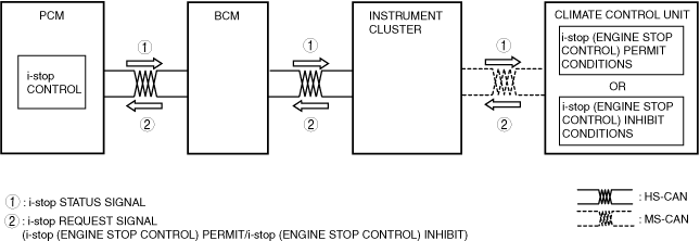
• The climate control unit determines i-stop control (engine stop control) according to the operation condition of the air conditioner system and sends i-stop (engine stop control) request signals to the PCM.
• The climate control unit controls the air mix actuator according to the change in the airflow temperature passing through the heater core or the evaporator during i-stop operation (engine stop control) as follows and corrects the airflow temperature.
-
― If airflow temperature passing through heater core decreases, air mix actuator is opened in HOT direction
― If airflow temperature passing through evaporator increases, air mix actuator is opened in COLD direction
-
Caution
-
• Occupants may hear the sound of the air mix actuator operating because there is no engine sound during the i-stop operation (engine stop control). The airflow temperature control is performed even during i-stop operation (engine stop control), therefore, it does not indicate a system malfunction even if the operation sound of the air mix actuator is heard.
Structure/Construction
Block diagram
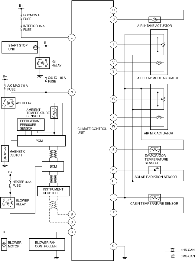
System wiring diagram
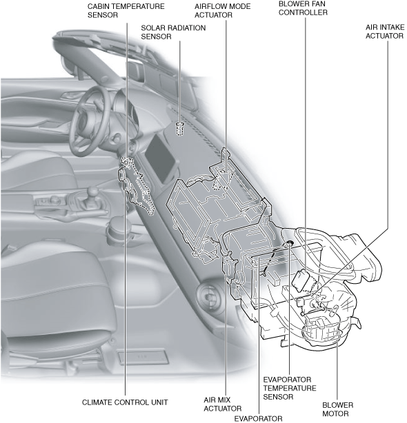
Structural view
Operation
Airflow temperature control
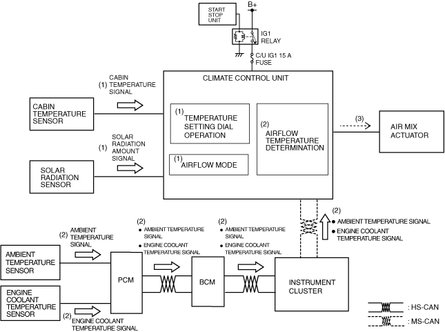
1. Based on the signals (1) from each sensor which change according to the temperature setting dial operation and the vehicle conditions, the climate control unit performs airflow temperature determination (2) when the ignition is switched ON (engine off or on).
2. The climate control unit drives (3) the air mix actuator based on the results of the airflow temperature determination and corrections.
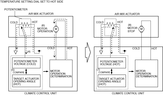
3. The climate control unit detects the current air mix actuator opening angle based on the potentiometer voltage (4).
4. The climate control unit compares (5) the target actuator opening angle with the potentiometer voltage.
5. When the potentiometer voltage differs from the target actuator opening angle, the climate control unit drives (6) the air mix actuator motor.
6. When the potentiometer voltage matches (7) the target actuator opening angle, the climate control unit stops (8) the air mix actuator motor.
Airflow volume control
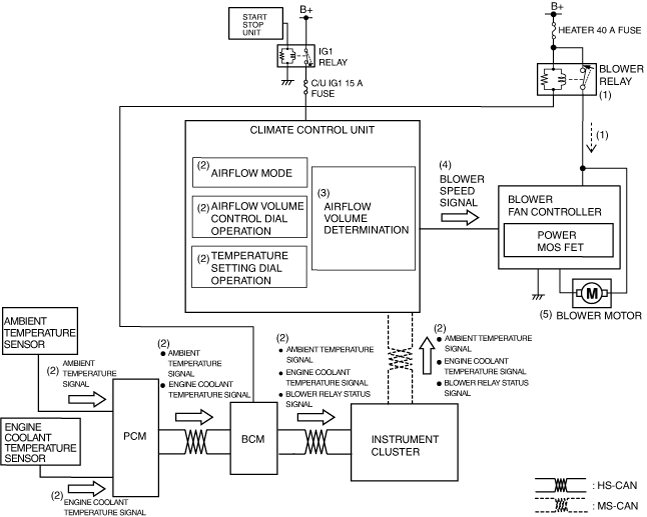
1. When the ignition is switched ON (engine off or on), the BCM turns the blower relay on (1).
2. When the blower relay turns on, the blower fan controller goes on operation standby.
3. Based on the operation of the airflow volume control dial and the temperature setting dial, the airflow mode condition, and the signals from each sensor (2), the climate control unit performs airflow volume determination (3) when the ignition is switched ON (engine off or on).
4. The climate control unit sends a blower speed signal (4) to the blower fan controller based on the results of the airflow volume determination and the corrections.
5. The blower fan controller operates (5) the blower motor based on the blower speed signal.
Airflow mode control
1. Based on the mode dial operation and the signals (1) from each sensor which change according to the vehicle conditions, the climate control unit performs airflow mode determination (2) when the ignition is switched ON (engine off or on).
2. The climate control unit drives (3) the airflow mode actuator based on the results of the airflow mode determination and corrections.
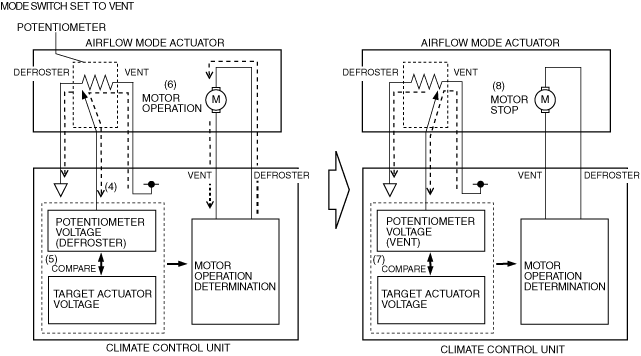
3. The climate control unit detects the current airflow mode actuator opening angle based on the potentiometer voltage (4).
4. The climate control unit compares (5) the target actuator voltage with the potentiometer voltage.
5. When the potentiometer voltage differs from the target actuator voltage, the climate control unit drives (6) the airflow mode actuator motor.
6. When the potentiometer voltage matches (7) the target actuator voltage, the climate control unit stops (8) the airflow mode actuator motor.
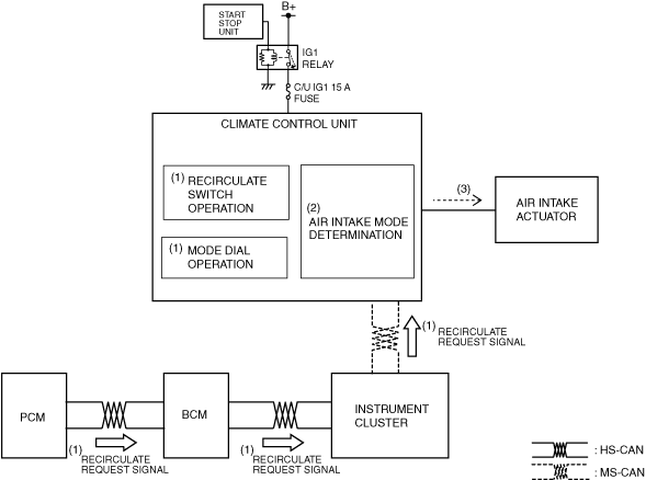
Air intake control
1. The climate control unit performs air intake mode determination (2) based on the signals (1) from the operation of the recirculate switch and the mode dial and the PCM when the ignition is switched ON (engine off or on).
2. The climate control unit drives (3) the air intake actuator based on the results of the air intake mode determination and corrections.
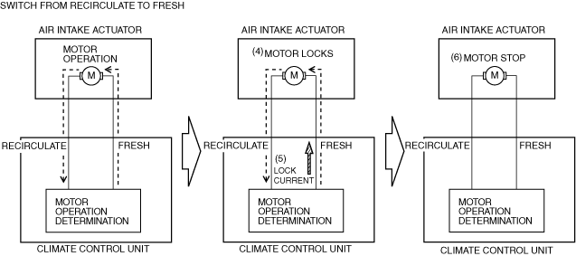
3. When the air intake actuator moves to FRESH or RECIRCULATE, the motor locks (4).
4. If the motor locks and is under excessive load, the current flowing from the climate control unit increases more than the specification. (Lock current)
5. When the climate control unit detects lock current (5), it stops (6) the air intake actuator motor.
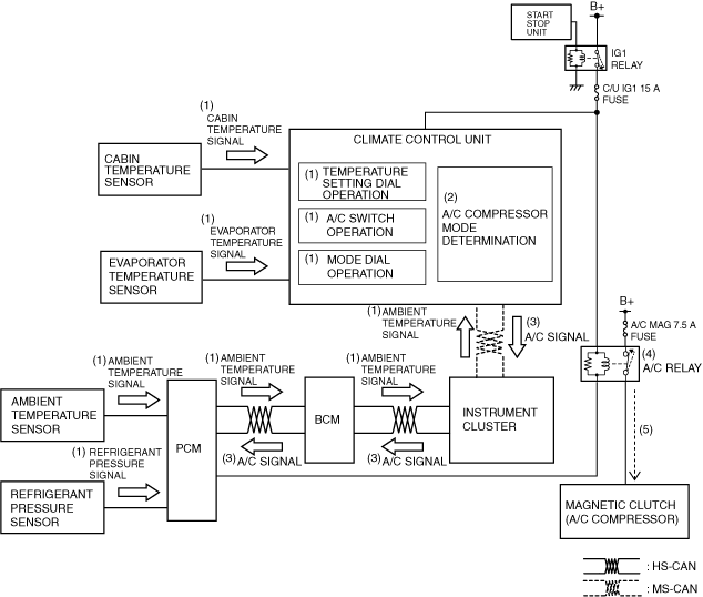
A/C compressor control
1. Based on the operation of each switch/dial and signals (1) from each sensor which change according to the vehicle conditions, the climate control unit performs A/C compressor mode determination (2) when the ignition is switched ON (engine off or on).
2. The climate control unit sends (3) the A/C signal to the PCM according to the result of the A/C compressor mode determination and corrections.
3. The PCM turns the A/C relay on (4) based on the A/C signal and the signals from each sensor which change according to the vehicle conditions.
4. When the A/C relay turns on, the magnetic clutch turns on (5).
Air conditioner i-stop control (With i-stop)
-
i-stop (engine stop control) request control (i-stop inhibit/i-stop permit)
-
• The climate control unit sends an i-stop inhibit or permit request signal to the PCM according to the operation conditions of the air conditioner system.
• If any of the following i-stop inhibit conditions is met, the climate control unit sends an i-stop inhibit request signal to the PCM.
i-stop inhibit conditions
|
1
|
Climate control unit detects DTC
|
|
2
|
Ambient temperature is -10 °C {14 °F} or less, or 50 °C {122 °F} or more
|
|
3
|
Rear window defogger switch is on
|
|
4
|
Blower motor is operating
|
Defroster is being operated manually
|
|
5
|
Airflow volume setting of airflow volume control dial is at 7th
|
|
6
|
A/C switch is ON
|
Set temperature is at MAX COLD
|
|
7
|
Airflow mode is VENT or BI-LEVEL
|
|
8
|
Large difference between set temperature and cabin temperature and difference between target airflow temperature and current airflow temperature
|
-
• When all of the i-stop inhibit conditions are met, the climate control unit sends an i-stop permit request signal to the PCM.
-
Air conditioner system control during i-stop (engine-stop control)
-
• When the climate control unit determines that the engine is stopped based on the i-stop condition signal sent from the PCM, it starts the air conditioner system control for the engine-stop condition.
• When the engine is stopped by the i-stop control, the climate control unit stops the air intake actuator at the current position.
-
Note
-
• If the engine is stopped by the i-stop control with the A/C switch turned on, the indicator on the A/C switch is kept turned on.
• Based on the following signals, the climate control unit calculates the engine coolant temperature correction value for the engine-stop condition by i-stop control.
-
― Engine coolant temperature signal at moment engine is stopped which is sent from PCM via CAN communication
― Heater core temperature
-
Recovery to normal air conditioner system control
-
• If any of the following i-stop inhibit conditions is met during air conditioner system control when the engine is stopped, the climate control unit sends an engine re-start request signal to the PCM.
• After sending an engine restart request signal, the climate control unit returns to normal air conditioner system control when the engine is restarted.