MANUAL AIR CONDITIONER SYSTEM [MANUAL AIR CONDITIONER]
id0740a2005000
Outline
• The climate control unit performs the following controls based on the signals from each switch/dial and the sensor.
-
― Airflow temperature control
― Airflow volume control
― Airflow mode control
― Air intake control
― A/C compressor control
― Air conditioner i-stop control (With i-stop)
Function
Airflow temperature control
-
• The airflow temperature control operates the air mix actuator and switches the air mix damper position in conjunction with the airflow temperature setting.
Airflow volume control
-
• The airflow volume control changes the blower motor control speed and switches the airflow volume in conjunction with the airflow volume setting.
Airflow mode control
-
• The airflow mode control operates the airflow mode actuator and switches the airflow mode door position in conjunction with the airflow mode setting.
Air intake control
-
• The air intake control operates the air intake actuator and switches the air intake door position in conjunction with the air intake setting and the vehicle conditions.
A/C compressor control
-
• The A/C compressor control sends the A/C signal to the PCM based on the climate control unit operation and signals from each sensor.
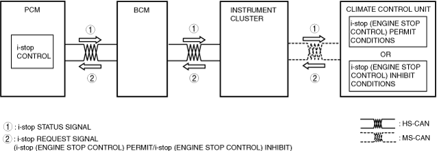
Air conditioner i-stop control (With i-stop)
-
• The climate control unit determines i-stop control (engine stop control) according to the operation condition of the air conditioner system and sends i-stop (engine stop control) request signals to the PCM.
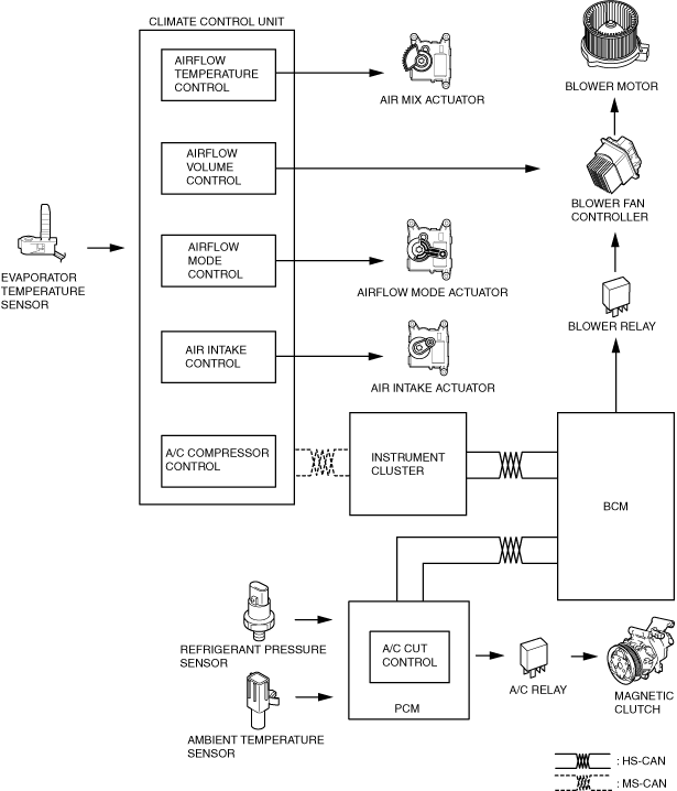
Structure/Construction
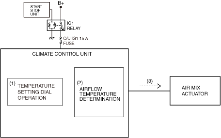
Block diagram
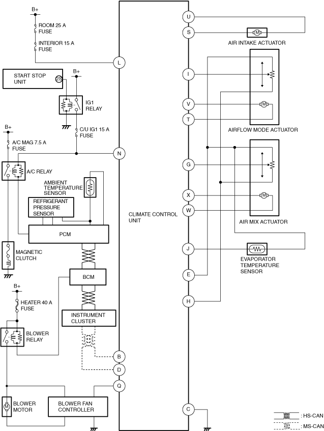
System wiring diagram
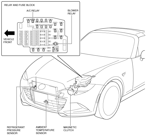
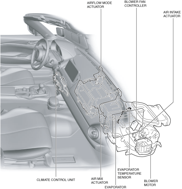
Structural view
Operation
Airflow temperature control
1. The climate control unit performs airflow temperature determination (2) based on the temperature setting dial operation (1) when the ignition is switched ON (engine off or on).
2. The climate control unit drives (3) the air mix actuator based on the results of the airflow temperature determination and corrections.
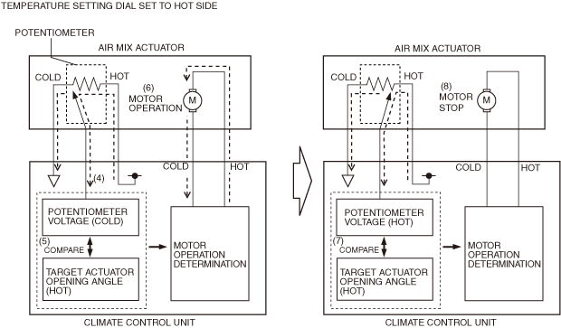
3. The climate control unit detects the current air mix actuator opening angle based on the potentiometer voltage (4).
4. The climate control unit compares (5) the target actuator opening angle with the voltage from the potentiometer.
5. When the potentiometer voltage value differs from the target actuator opening angle, the climate control unit drives (6) the air mix actuator motor.
6. When the potentiometer voltage value matches (7) the target actuator opening angle, the climate control unit stops (8) the air mix actuator motor.
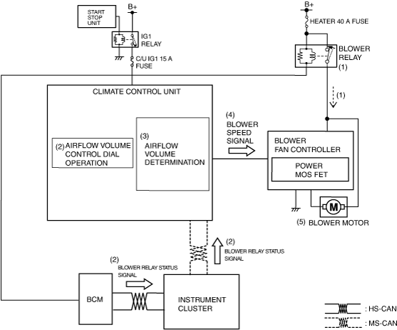
Airflow volume control
1. When the ignition is switched ON (engine off or on), the BCM turns the blower relay on (1).
2. When the blower relay turns on, the blower fan controller goes on operation standby.
3. Based on the operation of the airflow volume control dial (2), the climate control unit performs airflow volume determination (3) when the ignition is switched ON (engine off or on).
4. The climate control unit sends a blower speed signal (4) to the blower fan controller based on the results of the airflow volume determination and the corrections.
5. The blower fan controller operates (5) the blower motor based on the blower speed signal.
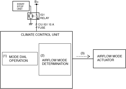
Airflow mode control
1. The climate control unit performs airflow mode determination (2) based on the mode dial operation (1) when the ignition is switched ON (engine off or on).
2. The climate control unit drives the airflow mode actuator (3) according to the results of the airflow mode determination and corrections.
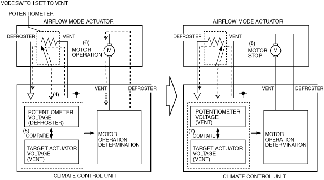
3. The climate control unit detects the current airflow mode actuator opening angle based on the potentiometer voltage (4).
4. The climate control unit compares (5) the target actuator voltage value with the voltage from the potentiometer.
5. When the potentiometer voltage value differs from the target actuator voltage value, the climate control unit drives (6) the airflow mode actuator motor.
6. When the potentiometer voltage value matches (7) the target actuator voltage value, the climate control unit stops (8) the airflow mode actuator motor.
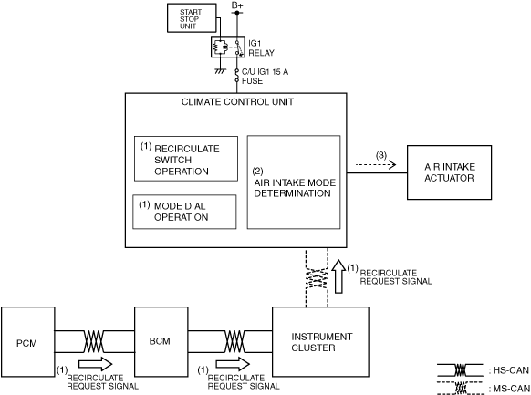
Air intake control
1. The climate control unit performs air intake mode determination (2) based on the signals (1) from the operation of the recirculate switch and the mode dial and the PCM when the ignition is switched ON (engine off or on).
2. The climate control unit drives the air intake actuator (3) according to the result of the air intake mode determination and corrections.
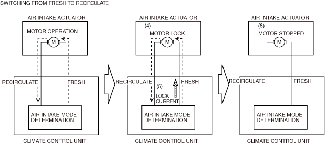
3. When the air intake actuator moves to FRESH or REC, the motor locks (4).
4. When the motor locks and is under excessive load, the current value flowing from the climate control unit increases more than the specification (lock current).
5. When the lock current (5) is detected, the climate control unit stops the motor drive signal (6) to the air intake actuator.
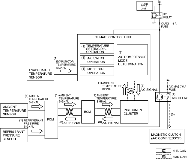
A/C compressor control
1. Based on the operation of each switch/dial and signals (1) from each sensor which change according to the vehicle conditions, the climate control unit performs A/C compressor mode determination (2) when the ignition is switched ON (engine off or on).
2. The climate control unit sends (3) the A/C signal to the PCM according to the result of the A/C compressor mode determination and corrections.
3. The PCM turns the A/C relay on (4) based on the A/C signal and the signals from each sensor which change according to the vehicle conditions.
4. When the A/C relay turns on, the magnetic clutch turns on (5).
Air conditioner i-stop control (With i-stop)
-
i-stop request control (i-stop (engine stop control) permission)
-
• The climate control unit sends an i-stop (engine stop control) permission request signal to the PCM in conjunction with the operation conditions of the air conditioner system.
-
i-stop (engine stop control) permission request
-
• The climate control unit sends an i-stop (engine-stop control) permit signal to the PCM when it does not detect any of the following conditions:
i-stop (engine stop control) inhibit conditions
|
No.
|
Item
|
Vehicle condition
|
|
1
|
• Airflow mode
• Blower motor
|
• Airflow mode during defrost
• Airflow volume setting of airflow volume control dial is at 7th
|
|
2
|
Ambient temperature
|
Ambient temperature is -10 °C {14 °F} or below, or 50 °C {122 °F} or more
|
|
3
|
Engine coolant temperature
|
When the fan switch is on, the engine coolant temperature does not meet the i-stop permit conditions (comfortable cabin temperature control not performed)
|
|
4
|
Evaporator temperature
|
When the A/C switch is on, the evaporator temperature does not meet the i-stop permit conditions (comfortable cabin temperature control not performed)
|