 |
amxzzw00004942
AIRFLOW MODE ACTUATOR INSPECTION [MANUAL AIR CONDITIONER]
id0740a2801700
L.H.D.
1. Disconnect the negative battery terminal. (See NEGATIVE BATTERY TERMINAL DISCONNECTION/CONNECTION.)
2. Remove the airflow mode actuator. (See AIRFLOW MODE ACTUATOR REMOVAL/INSTALLATION [MANUAL AIR CONDITIONER].)
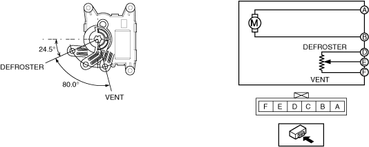
3. Apply battery positive voltage and connect the ground to the airflow mode actuator terminals as indicated in the table below and verify the operation condition.
|
B+ Terminal |
Ground Terminal |
Operation |
|---|---|---|
|
A
|
B
|
VENT → DEFROSTER
|
|
B
|
A
|
DEFROSTER → VENT
|
amxzzw00004942
|
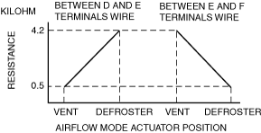
4. Verify that the resistance between terminals D and E, E and F matches the airflow mode actuator operation as shown in the graph.
amxzzw00004943
|
R.H.D.
1. Disconnect the negative battery terminal. (See NEGATIVE BATTERY TERMINAL DISCONNECTION/CONNECTION.)
2. Remove the airflow mode actuator. (See AIRFLOW MODE ACTUATOR REMOVAL/INSTALLATION [MANUAL AIR CONDITIONER].)
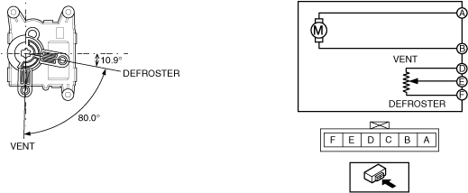
3. Apply battery positive voltage and connect the ground to the airflow mode actuator terminals as indicated in the table below and verify the operation condition.
|
B+ Terminal |
Ground Terminal |
Operation |
|---|---|---|
|
A
|
B
|
DEFROSTER → VENT
|
|
B
|
A
|
VENT → DEFROSTER
|
amxzzw00004944
|
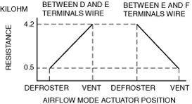
4. Verify that the resistance between terminals D and E, E and F matches the airflow mode actuator operation as shown in the graph.
amxzzw00004945
|