|
1
|
VERIFY IF MALFUNCTION CAUSE IS OPERATION UNDER OPERATION PERMISSION CONDITION
• Perform the power window system initialization procedure.
• Does the passenger-side door glass operate automatically using the power window sub switch?
|
Yes
|
System is normal. (Tell the customer about power window system initialization procedure.)
|
|
No
|
Go to the next step.
|
|
2
|
POWER WINDOW SUB SWITCH CONNECTOR INSPECTION
• Switch the ignition off.
• Disconnect the negative battery terminal.
• Disconnect the power window sub switch connector.
• Inspect the connector engagement and connection condition and inspect the terminals for damage, deformation, corrosion, or disconnection.
• Is the connector normal?
|
Yes
|
Go to the next step.
|
|
No
|
Repair or replace the connector, then go to Step 10.
|
|
3
|
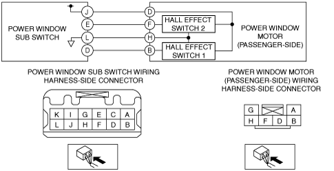
POWER WINDOW MOTOR (PASSENGER-SIDE) CONNECTOR INSPECTION
• Disconnect the power window motor (passenger-side) connector.
• Inspect the connector engagement and connection condition and inspect the terminals for damage, deformation, corrosion, or disconnection.
• Is the connector normal?
|
Yes
|
Go to the next step.
|
|
No
|
Repair or replace the connector, then go to Step 10.
|
|
4
|
POWER WINDOW MOTOR (PASSENGER-SIDE) TERMINAL D INSPECTION
• Reconnect all the disconnected connectors.
• Connect the negative battery terminal.
• Measure the voltage at the power window motor (passenger-side) terminal D (vehicle wiring harness side).
• Is the voltage B+?
|
Yes
|
Go to Step 6.
|
|
No
|
Go to the next step.
|
|
5
|
POWER WINDOW SUB SWITCH TERMINAL J INSPECTION
• Measure the voltage at power window sub switch terminal J (vehicle wiring harness side).
• Is the voltage B+?
|
Yes
|
Refer to the wiring diagram and verify if there is a common connector between power window sub switch terminal J and power window motor (passenger-side) terminal D.
If there is a common connector:
• Inspect the common connector and terminals for corrosion, damage, or disconnection and the common wiring harnesses for an open or short circuit to determine the malfunctioning location.
• Repair or replace the malfunctioning location.
If there is no common connector:
• Repair or replace the wiring harness which has an open or short circuit.
Go to Step 10.
|
|
No
|
Replace the power window sub switch, then go to Step 10.
|
|
6
|
DETERMINE IF MALFUNCTION CAUSE IS POWER WINDOW SUB SWITCH INTERNAL GROUND SYSTEM
• Disconnect the negative battery terminal.
• Inspect for continuity between power window motor (passenger-side) terminal H (vehicle wiring harness side) and body ground.
• Is there continuity?
|
Yes
|
Go to Step 8.
|
|
No
|
Go to the next step.
|
|
7
|
VERIFY IF MALFUNCTION CAUSE IS OPEN CIRCUIT IN WIRING HARNESS BETWEEN POWER WINDOW SUB SWITCH AND POWER WINDOW MOTOR (PASSENGER-SIDE)
• Disconnect the power window sub switch connector and power window motor (passenger-side) connector.
• Inspect for continuity between the following terminals (vehicle wiring harness).
-
― Power window sub switch terminal L and power window motor (passenger-side) terminal H
• Is there continuity?
|
Yes
|
Replace the power window sub switch, then go to Step 10.
|
|
No
|
Refer to the wiring diagram and verify if there is a common connector between power window sub switch terminal L and power window motor (passenger-side) terminal H.
If there is a common connector:
• Inspect the common connector and terminals for corrosion, damage, or disconnection and the common wiring harnesses for an open circuit to determine the malfunctioning location.
• Repair or replace the malfunctioning location.
If there is no common connector:
• Repair or replace the wiring harness which has an open circuit.
Go to Step 10.
|
|
8
|
POWER WINDOW SUB SWITCH TERMINALS D AND E INSPECTION
• Reconnect all the disconnected connectors.
• Connect the negative battery terminal.
• Switch the ignition ON (engine off or on).
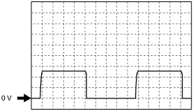
• Operate the passenger-side power window to measure the pulse at power window sub switch terminals D and E.
• Measure the pulse at power window sub switch terminals D and E.
• Is the pulse normal?
|
Yes
|
-
Note
-
• The power window motor (passenger-side) is normal because the pulse sent from the power window motor (passenger-side) to the power window sub switch is normal.
Replace the power window sub switch, then go to Step 10.
|
|
No
|
Go to the next step.
|
|
9
|
POWER WINDOW MOTOR (PASSENGER-SIDE) TERMINALS B AND F INSPECTION
• Operate the passenger-side power window to measure the pulse at power window motor (passenger-side) terminals B and F.
• Is the pulse normal?
|
Yes
|
Refer to the wiring diagram and verify if there is a common connector between the following terminals.
• Power window sub switch terminal D and power window motor (passenger-side) terminal B
• Power window sub switch terminal E and power window motor (passenger-side) terminal F
If there is a common connector:
• Inspect the common connector and terminals for corrosion, damage, or disconnection and the common wiring harnesses for an open or short circuit to determine the malfunctioning location.
• Repair or replace the malfunctioning location.
If there is no common connector:
• Repair or replace the wiring harness which has an open or short circuit.
Go to the next step.
|
|
No
|
Replace the power window motor (passenger-side), then go to the next step.
|
|
10
|
VERIFY IF MALFUNCTION CAUSE IS CORRECTED
• Does the power window system operate normally?
|
Yes
|
Troubleshooting completed. (Explain the problem to the customer.)
|
|
No
|
Verify the malfunction symptom in the symptom troubleshooting chart and perform the other applicable malfunction diagnosis.
|