|
ac5wzw00010371
THE HEADLIGHT AUTO LEVELING SYSTEM DOES NOT OPERATE IN RESPONSE TO VEHICLE POSTURE [HEADLIGHT AUTO LEVELING SYSTEM]
id0903d0013800
With Auto Leveling Control Module
Description
Possible malfunction
System wiring diagram
ac5wzw00010371
|
Diagnostic Procedure
|
Step |
Inspection |
Action |
|
|---|---|---|---|
|
1
|
DETERMINE IF MALFUNCTIONING LOCATION IS AUTO LEVELING SENSOR
• Verify the malfunction symptom.
• Does only one side of the headlight auto leveling system operate?
|
Yes
|
Go to the next step.
|
|
No
|
Go to Step 6.
|
||
|
2
|
LEVELING OPERATION SIGNAL INSPECTION
• Using the M-MDS, perform the headlight leveling actuator operation check mode.
• Does the headlight leveling actuator operate normally?
|
Yes
|
Go to Step 8.
|
|
No
|
Go to the next step.
|
||
|
3
|
INSPECT LEVELING OPERATION SIGNAL CIRCUIT FOR OPEN CIRCUIT
• Inspect the wiring harness for continuity between the auto leveling control module and headlight leveling actuator on the side in which the auto leveling system does not operate.
• Is there continuity?
|
Yes
|
Go to the next step.
|
|
No
|
Refer to the wiring diagram and verify if there is a common connector between auto leveling control module terminal O and headlight leveling actuator (LH)/(RH) terminal F.
If there is a common connector:
• Inspect the common connector and terminals for corrosion, damage, or disconnection and the common wiring harnesses for an open circuit to determine the malfunctioning location.
• Repair or replace the malfunctioning location and go to Step 9.
If there is no common connector:
• Repair or replace the wiring harness which has an open circuit and go to Step 9.
|
||
|
4
|
INSPECT LEVELING OPERATION SIGNAL CIRCUIT FOR SHORT TO GROUND
• Inspect for continuity between the ground and the wiring harness between the auto leveling control module and headlight leveling actuator on the side in which the auto leveling system does not operate.
• Is there continuity?
|
Yes
|
Refer to the wiring diagram and verify if there is a common connector between auto leveling control module terminal O and headlight leveling actuator (LH)/(RH) terminal F.
If there is a common connector:
• Inspect the common connector and terminals for corrosion, damage, or disconnection and the common wiring harnesses for short to ground to determine the malfunctioning location.
• Repair or replace the malfunctioning location and go to Step 9.
If there is no common connector:
• Repair or replace the wiring harness which is shorted to ground and go to Step 9.
|
|
No
|
Go to the next step.
|
||
|
5
|
DETERMINE IF MALFUNCTION CAUSE IS HEADLIGHT LEVELING ACTUATOR OR AUTO LEVELING CONTROL MODULE
• Replace the front combination light in which the auto leveling system does not operate.
• Does the auto leveling system operate correctly?
|
Yes
|
Troubleshooting completed.
|
|
No
|
Replace the auto leveling control module and go to Step 9.
|
||
|
6
|
INSPECT WIRING HARNESS BETWEEN HEADLIGHT LEVELING ACTUATOR AND AUTO LEVELING CONTROL MODULE FOR OPEN CIRCUIT
• Inspect for continuity in the wiring harness between the following terminals:
• Is there continuity?
|
Yes
|
Go to the next step.
|
|
No
|
Refer to the wiring diagram and verify if there is a common connector between the following terminals.
• Auto leveling control module terminal P—Headlight leveling actuator (LH)/(RH) terminal I
• Auto leveling control module terminal O—Headlight leveling actuator (LH)/(RH) terminal F
• Auto leveling control module terminal M—Headlight leveling actuator (LH)/(RH) terminal L
If there is a common connector:
• Inspect the common connector and terminals for corrosion, damage, or disconnection and the common wiring harnesses for an open circuit to determine the malfunctioning location.
• Repair or replace the malfunctioning location and go to Step 9.
If there is no common connector:
• Repair or replace the wiring harness which has an open circuit and go to Step 9.
|
||
|
7
|
INSPECT WIRING HARNESS BETWEEN HEADLIGHT LEVELING ACTUATOR AND AUTO LEVELING CONTROL MODULE FOR SHORT TO GROUND
• Inspect for continuity between body ground and the following terminals.
• Is there continuity?
|
Yes
|
Refer to the wiring diagram and verify if there is a common connector between the following terminals.
• Auto leveling control module terminal P—Headlight leveling actuator (LH)/(RH) terminal I
• Auto leveling control module terminal O—Headlight leveling actuator (LH)/(RH) terminal F
• Auto leveling control module terminal M—Headlight leveling actuator (LH)/(RH) terminal L
If there is a common connector:
• Inspect the common connector and terminals for corrosion, damage, or disconnection and the common wiring harnesses for short to ground to determine the malfunctioning location.
• Repair or replace the malfunctioning location and go to Step 9.
If there is no common connector:
• Repair or replace the wiring harness which is shorted to ground and go to Step 9.
|
|
No
|
Go to the next step.
|
||
|
8
|
VERIFY AUTO LEVELING SENSOR INSTALLATION
• Verify the auto leveling sensor installation condition.
• Is a bracket bent, is there damage, or is a link disconnected?
|
Yes
|
Repair or replace the malfunctioning location and go to the next step.
|
|
No
|
Go to the next step.
|
||
|
9
|
VERIFY IF MALFUNCTION IS RESOLVED
• Has the malfunction symptom been eliminated?
|
Yes
|
Troubleshooting completed. (explain the contents of the servicing to the customer)
|
|
No
|
Repeat the diagnosis from Step 1.
If the malfunction has not been resolved, replace the auto leveling control module.
|
||
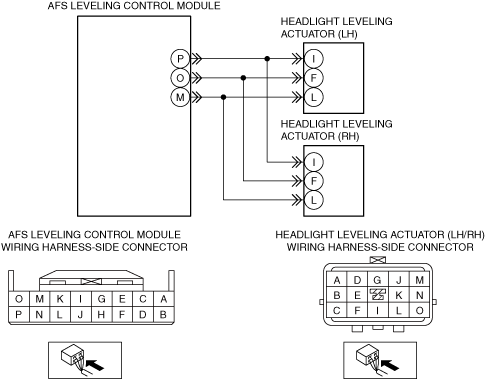
With AFS Control Module
Description
Possible malfunction
System wiring diagram
ac8wzw00002318
|
Diagnostic Procedure
|
Step |
Inspection |
Action |
|
|---|---|---|---|
|
1
|
DETERMINE IF MALFUNCTIONING LOCATION IS AUTO LEVELING SENSOR
• Verify the malfunction symptom.
• Does only one side of the headlight auto leveling system operate?
|
Yes
|
Go to the next step.
|
|
No
|
Go to Step 6.
|
||
|
2
|
LEVELING OPERATION SIGNAL INSPECTION
• Using the M-MDS, perform the headlight leveling actuator operation check mode.
• Does the headlight leveling actuator operate normally?
|
Yes
|
Go to Step 8.
|
|
No
|
Go to the next step.
|
||
|
3
|
INSPECT LEVELING OPERATION SIGNAL CIRCUIT FOR OPEN CIRCUIT
• Inspect the wiring harness for continuity between the AFS control module and headlight leveling actuator on the side in which the auto leveling system does not operate.
• Is there continuity?
|
Yes
|
Go to the next step.
|
|
No
|
Refer to the wiring diagram and verify if there is a common connector between AFS control module terminal O and headlight leveling actuator (LH)/(RH) terminal F.
If there is a common connector:
• Inspect the common connector and terminals for corrosion, damage, or disconnection and the common wiring harnesses for an open circuit to determine the malfunctioning location.
• Repair or replace the malfunctioning location and go to Step 9.
If there is no common connector:
• Repair or replace the wiring harness which has an open circuit and go to Step 9.
|
||
|
4
|
INSPECT LEVELING OPERATION SIGNAL CIRCUIT FOR SHORT TO GROUND
• Inspect for continuity between the ground and the wiring harness between the AFS control module and headlight leveling actuator on the side in which the auto leveling system does not operate.
• Is there continuity?
|
Yes
|
Refer to the wiring diagram and verify if there is a common connector between AFS control module terminal O and headlight leveling actuator (LH)/(RH) terminal F.
If there is a common connector:
• Inspect the common connector and terminals for corrosion, damage, or disconnection and the common wiring harnesses for short to ground to determine the malfunctioning location.
• Repair or replace the malfunctioning location and go to Step 9.
If there is no common connector:
• Repair or replace the wiring harness which is shorted to ground and go to Step 9.
|
|
No
|
Go to the next step.
|
||
|
5
|
DETERMINE IF MALFUNCTION CAUSE IS HEADLIGHT LEVELING ACTUATOR OR AFS CONTROL MODULE
• Replace the front combination light in which the auto leveling system does not operate.
• Does the auto leveling system operate correctly?
|
Yes
|
Troubleshooting completed.
|
|
No
|
Replace the AFS control module and go to Step 9.
|
||
|
6
|
INSPECT WIRING HARNESS BETWEEN HEADLIGHT LEVELING ACTUATOR AND AFS CONTROL MODULE FOR OPEN CIRCUIT
• Inspect for continuity in the wiring harness between the following terminals:
• Is there continuity?
|
Yes
|
Go to the next step.
|
|
No
|
Refer to the wiring diagram and verify if there is a common connector between the following terminals.
• AFS control module terminal P—Headlight leveling actuator (LH)/(RH) terminal I
• AFS control module terminal O—Headlight leveling actuator (LH)/(RH) terminal F
• AFS control module terminal M—Headlight leveling actuator (LH)/(RH) terminal L
If there is a common connector:
• Inspect the common connector and terminals for corrosion, damage, or disconnection and the common wiring harnesses for an open circuit to determine the malfunctioning location.
• Repair or replace the malfunctioning location and go to Step 9.
If there is no common connector:
• Repair or replace the wiring harness which has an open circuit and go to Step 9.
|
||
|
7
|
INSPECT WIRING HARNESS BETWEEN HEADLIGHT LEVELING ACTUATOR AND AFS CONTROL MODULE FOR SHORT TO GROUND
• Inspect for continuity between body ground and the following terminals.
• Is there continuity?
|
Yes
|
Refer to the wiring diagram and verify if there is a common connector between the following terminals.
• AFS control module terminal P—Headlight leveling actuator (LH)/(RH) terminal I
• AFS control module terminal O—Headlight leveling actuator (LH)/(RH) terminal F
• AFS control module terminal M—Headlight leveling actuator (LH)/(RH) terminal L
If there is a common connector:
• Inspect the common connector and terminals for corrosion, damage, or disconnection and the common wiring harnesses for short to ground to determine the malfunctioning location.
• Repair or replace the malfunctioning location and go to Step 9.
If there is no common connector:
• Repair or replace the wiring harness which is shorted to ground and go to Step 9.
|
|
No
|
Go to the next step.
|
||
|
8
|
VERIFY AUTO LEVELING SENSOR INSTALLATION
• Verify the auto leveling sensor installation condition.
• Is a bracket bent, is there damage, or is a link disconnected?
|
Yes
|
Repair or replace the malfunctioning location and go to the next step.
|
|
No
|
Go to the next step.
|
||
|
9
|
VERIFY IF MALFUNCTION IS RESOLVED
• Has the malfunction symptom been eliminated?
|
Yes
|
Troubleshooting completed. (explain the contents of the servicing to the customer)
|
|
No
|
Repeat the diagnosis from Step 1.
If the malfunction has not been resolved, replace the AFS control module.
|
||
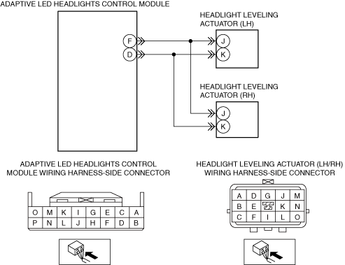
With Adaptive LED Headlights Control Module
Description
Possible malfunction
System wiring diagram
ac8wzw00002319
|
Diagnostic Procedure
|
Step |
Inspection |
Action |
|
|---|---|---|---|
|
1
|
DETERMINE IF MALFUNCTIONING LOCATION IS AUTO LEVELING SENSOR
• Verify the malfunction symptom.
• Does only one side of the headlight auto leveling system operate?
|
Yes
|
Go to the next step.
|
|
No
|
Go to Step 6.
|
||
|
2
|
LEVELING OPERATION SIGNAL INSPECTION
• Using the M-MDS, perform the headlight leveling actuator operation check mode.
• Does the headlight leveling actuator operate normally?
|
Yes
|
Go to Step 8.
|
|
No
|
Go to the next step.
|
||
|
3
|
INSPECT LEVELING OPERATION SIGNAL CIRCUIT FOR OPEN CIRCUIT
• Inspect the wiring harness for continuity between the adaptive LED headlights control module and headlight leveling actuator on the side in which the auto leveling system does not operate.
• Is there continuity?
|
Yes
|
Go to the next step.
|
|
No
|
Refer to the wiring diagram and verify if there is a common connector between adaptive LED headlights control module terminal D and headlight leveling actuator (LH)/(RH) terminal K.
If there is a common connector:
• Inspect the common connector and terminals for corrosion, damage, or disconnection and the common wiring harnesses for an open circuit to determine the malfunctioning location.
• Repair or replace the malfunctioning location and go to Step 9.
If there is no common connector:
• Repair or replace the wiring harness which has an open circuit and go to Step 9.
|
||
|
4
|
INSPECT LEVELING OPERATION SIGNAL CIRCUIT FOR SHORT TO GROUND
• Inspect for continuity between the ground and the wiring harness between the adaptive LED headlights control module and headlight leveling actuator on the side in which the auto leveling system does not operate.
• Is there continuity?
|
Yes
|
Refer to the wiring diagram and verify if there is a common connector between adaptive LED headlights control module terminal D and headlight leveling actuator (LH)/(RH) terminal K.
If there is a common connector:
• Inspect the common connector and terminals for corrosion, damage, or disconnection and the common wiring harnesses for short to ground to determine the malfunctioning location.
• Repair or replace the malfunctioning location and go to Step 9.
If there is no common connector:
• Repair or replace the wiring harness which is shorted to ground and go to Step 9.
|
|
No
|
Go to the next step.
|
||
|
5
|
DETERMINE IF MALFUNCTION CAUSE IS HEADLIGHT LEVELING ACTUATOR OR ADAPTIVE LED HEADLIGHTS CONTROL MODULE
• Replace the front combination light in which the auto leveling system does not operate.
• Does the auto leveling system operate correctly?
|
Yes
|
Troubleshooting completed.
|
|
No
|
Replace the adaptive LED headlights control module and go to Step 9.
|
||
|
6
|
INSPECT WIRING HARNESS BETWEEN HEADLIGHT LEVELING ACTUATOR AND ADAPTIVE LED HEADLIGHTS CONTROL MODULE FOR OPEN CIRCUIT
• Inspect for continuity in the wiring harness between the following terminals:
• Is there continuity?
|
Yes
|
Go to the next step.
|
|
No
|
Refer to the wiring diagram and verify if there is a common connector between the following terminals.
• Adaptive LED headlights control module terminal D—Headlight leveling actuator (LH)/(RH) terminal K
• Adaptive LED headlights control module terminal F—Headlight leveling actuator (LH)/(RH) terminal J
If there is a common connector:
• Inspect the common connector and terminals for corrosion, damage, or disconnection and the common wiring harnesses for an open circuit to determine the malfunctioning location.
• Repair or replace the malfunctioning location and go to Step 9.
If there is no common connector:
• Repair or replace the wiring harness which has an open circuit and go to Step 9.
|
||
|
7
|
INSPECT WIRING HARNESS BETWEEN HEADLIGHT LEVELING ACTUATOR AND ADAPTIVE LED HEADLIGHTS CONTROL MODULE FOR SHORT TO GROUND
• Inspect for continuity between body ground and the following terminals.
• Is there continuity?
|
Yes
|
Refer to the wiring diagram and verify if there is a common connector between the following terminals.
• Adaptive LED headlights control module terminal D—Headlight leveling actuator (LH)/(RH) terminal K
• Adaptive LED headlights control module terminal F—Headlight leveling actuator (LH)/(RH) terminal J
If there is a common connector:
• Inspect the common connector and terminals for corrosion, damage, or disconnection and the common wiring harnesses for short to ground to determine the malfunctioning location.
• Repair or replace the malfunctioning location and go to Step 9.
If there is no common connector:
• Repair or replace the wiring harness which is shorted to ground and go to Step 9.
|
|
No
|
Go to the next step.
|
||
|
8
|
VERIFY AUTO LEVELING SENSOR INSTALLATION
• Verify the auto leveling sensor installation condition.
• Is a bracket bent, is there damage, or is a link disconnected?
|
Yes
|
Repair or replace the malfunctioning location and go to the next step.
|
|
No
|
Go to the next step.
|
||
|
9
|
VERIFY IF MALFUNCTION IS RESOLVED
• Has the malfunction symptom been eliminated?
|
Yes
|
Troubleshooting completed. (explain the contents of the servicing to the customer)
|
|
No
|
Repeat the diagnosis from Step 1.
If the malfunction has not been resolved, replace the adaptive LED headlights control module.
|
||