 |
amxzzw00005586
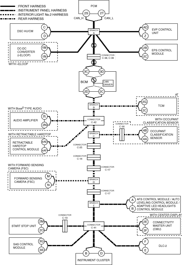
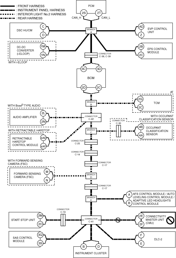
DETERMINING OPEN CIRCUIT LOCATION (HS-CAN) [L.H.D.]
id100225000400
1. Verify the CAN system-related module DTCs and the failed module on the M-MDS screen.
2. Apply the communication error DTC and the failed module to DTC output pattern and malfunctioning location, and select the possible cause for the diagnostic result and the reference for the inspection item. (See DTC Output Pattern And Malfunctioning Location.)
3. Inspect the possible cause and inspection item of the applicable malfunctioning part.
4. After repairs, return to CONTROLLER AREA NETWORK (CAN) MALFUNCTION DIAGNOSIS FLOW, and verify that the repairs have been completed. (See CONTROLLER AREA NETWORK (CAN) MALFUNCTION DIAGNOSIS FLOW [L.H.D.].)
DTC Output Pattern And Malfunctioning Location
|
M-MDS display |
DTC output pattern and malfunctioning location |
|||||||||||||||||||||
|---|---|---|---|---|---|---|---|---|---|---|---|---|---|---|---|---|---|---|---|---|---|---|
|
DTC output module |
DTC |
|||||||||||||||||||||
|
PCM
(PCM)
|
U0101:00
|
|
|
|
|
|
|
|
|
×
|
|
|
|
|
|
|
|
|
|
|
|
|
|
U0121:00
|
|
×
|
|
|
|
|
|
|
|
|
|
|
|
|
|
|
|
|
|
|
|
|
|
U0131:00
|
|
|
|
|
×
|
|
|
|
|
|
|
|
|
|
|
|
|
|
|
|
|
|
|
U0140:00
|
|
|
|
|
|
|
×
|
|
|
|
|
|
|
|
|
|
|
|
|
|
|
|
|
U0151:00
|
|
|
|
|
|
|
|
|
|
|
|
|
|
|
|
|
|
|
|
×
|
|
|
|
U0155:00
|
|
|
|
|
|
|
|
|
|
|
|
|
|
|
|
|
|
|
|
|
×
|
|
|
U0214:00
|
|
|
|
|
|
|
|
|
|
|
|
|
|
|
|
|
|
×
|
|
|
|
|
|
U023A:00
|
|
|
|
|
|
|
|
|
|
|
|
|
|
×
|
|
|
|
|
|
|
|
|
|
U0298:00
|
|
|
|
×
|
|
|
|
|
|
|
|
|
|
|
|
|
|
|
|
|
|
|
|
ABS
(DSC HU/CM)
|
U0100:00
|
×
|
|
|
|
|
|
|
|
|
|
|
|
|
|
|
|
|
|
|
|
|
|
U0101:00
|
|
|
|
|
|
|
|
|
×
|
|
|
|
|
|
|
|
|
|
|
|
|
|
|
U012B:00
|
|
|
×
|
|
|
|
|
|
|
|
|
|
|
|
|
|
|
|
|
|
|
|
|
U0131:00
|
|
|
|
|
×
|
|
|
|
|
|
|
|
|
|
|
|
|
|
|
|
|
|
|
U0140:00
|
|
|
|
|
|
|
×
|
|
|
|
|
|
|
|
|
|
|
|
|
|
|
|
|
U0151:00
|
|
|
|
|
|
|
|
|
|
|
|
|
|
|
|
|
|
|
|
×
|
|
|
|
U0155:00
|
|
|
|
|
|
|
|
|
|
|
|
|
|
|
|
|
|
|
|
|
×
|
|
|
U023A:00
|
|
|
|
|
|
|
|
|
|
|
|
|
|
×
|
|
|
|
|
|
|
|
|
|
EVP
(EVP control unit)
|
U0100:00
|
×
|
|
|
|
|
|
|
|
|
|
|
|
|
|
|
|
|
|
|
|
|
|
U0100:08
|
×
|
|
|
|
|
|
|
|
|
|
|
|
|
|
|
|
|
|
|
|
|
|
|
U0121:00
|
|
×
|
|
|
|
|
|
|
|
|
|
|
|
|
|
|
|
|
|
|
|
|
|
U0121:02
|
|
×
|
|
|
|
|
|
|
|
|
|
|
|
|
|
|
|
|
|
|
|
|
|
U0121:87
|
|
×
|
|
|
|
|
|
|
|
|
|
|
|
|
|
|
|
|
|
|
|
|
|
U0155:00
|
|
|
|
|
|
|
|
|
|
|
|
|
|
|
|
|
|
|
|
|
×
|
|
|
DCDC*1
(DC-DC converter (i-ELOOP))
|
U0100:00
|
×
|
|
|
|
|
|
|
|
|
|
|
|
|
|
|
|
|
|
|
|
|
|
U0140:00
|
|
|
|
|
|
|
×
|
|
|
|
|
|
|
|
|
|
|
|
|
|
|
|
|
U0151:00
|
|
|
|
|
|
|
|
|
|
|
|
|
|
|
|
|
|
|
|
×
|
|
|
|
U0155:00
|
|
|
|
|
|
|
|
|
|
|
|
|
|
|
|
|
|
|
|
|
×
|
|
|
EPS
(EPS control module)
|
U0100:00
|
×
|
|
|
|
|
|
|
|
|
|
|
|
|
|
|
|
|
|
|
|
|
|
U0121:00
|
|
×
|
|
|
|
|
|
|
|
|
|
|
|
|
|
|
|
|
|
|
|
|
|
U0155:00
|
|
|
|
|
|
|
|
|
|
|
|
|
|
|
|
|
|
|
|
|
×
|
|
|
BCM
(BCM)
|
U0100:00
|
×
|
|
|
|
|
×
|
|
|
|
|
|
|
|
|
|
|
|
|
|
|
|
|
U0101:00
|
|
|
|
|
|
|
|
|
×
|
|
|
|
|
|
|
|
|
|
|
|
|
|
|
U0121:00
|
|
×
|
|
|
|
×
|
|
|
|
|
|
|
|
|
|
|
|
|
|
|
|
|
|
U0151:00
|
|
|
|
|
|
|
|
|
|
|
|
|
|
|
|
|
|
|
|
×
|
|
|
|
U0155:00
|
|
|
|
|
|
|
|
|
|
|
|
|
|
|
|
|
|
|
|
|
×
|
|
|
U0214:00
|
|
|
|
|
|
|
|
|
|
|
|
|
|
|
|
|
|
×
|
|
|
|
|
|
U023A:00
|
|
|
|
|
|
|
|
|
|
|
|
|
|
×
|
|
|
|
|
|
|
|
|
|
TCM*2
(TCM)
|
U0100:00
|
×
|
|
|
|
|
×
|
|
×
|
|
|
|
|
|
|
|
|
|
|
|
|
|
|
U0121:00
|
|
×
|
|
|
|
×
|
|
×
|
|
|
|
|
|
|
|
|
|
|
|
|
|
|
|
U0131:00
|
|
|
|
|
×
|
×
|
|
×
|
|
|
|
|
|
|
|
|
|
|
|
|
|
|
|
U0155:00
|
|
|
|
|
|
|
|
|
|
|
|
|
|
|
|
|
|
|
|
|
×
|
|
|
U0214:00
|
|
|
|
|
|
|
|
|
|
|
|
|
|
|
|
|
|
×
|
|
|
|
|
|
RHT
(Retractable hardtop control module)
|
U0100:00
|
×
|
|
|
|
|
×
|
|
×
|
|
×
|
|
|
|
|
|
|
|
|
|
|
|
|
U0101:00
|
|
|
|
|
|
|
|
|
×
|
×
|
|
|
|
|
|
|
|
|
|
|
|
|
|
U0155:00
|
|
|
|
|
|
|
|
|
|
|
|
|
|
|
|
|
|
|
|
|
×
|
|
|
FSC*4
(Forward sensing camera (FSC))
|
U0100:00
|
×
|
|
|
|
|
×
|
|
×
|
|
×
|
|
|
×
|
|
|
|
|
|
|
|
|
|
U0121:00
|
|
×
|
|
|
|
×
|
|
×
|
|
×
|
|
|
×
|
|
|
|
|
|
|
|
|
|
|
U0131:00
|
|
|
|
|
×
|
×
|
|
×
|
|
×
|
|
|
×
|
|
|
|
|
|
|
|
|
|
|
U0140:00
|
|
|
|
|
|
|
×
|
×
|
|
×
|
|
|
×
|
|
|
|
|
|
|
|
||
|
U0151:00
|
|
|
|
|
|
|
|
|
|
|
|
|
|
|
|
|
|
|
|
×
|
|
|
|
U0155:00
|
|
|
|
|
|
|
|
|
|
|
|
|
|
|
|
|
|
|
|
×
|
||
|
U0156:00
|
|
|
|
|
|
|
|
|
|
|
|
|
|
|
|
|
|
|
×
|
|
|
|
|
U0182:00
|
|
|
|
|
|
|
|
|
|
|
|
|
|
|
|
×
|
|
|
|
|
||
|
U0214:00
|
|
|
|
|
|
|
|
|
|
|
|
|
|
|
|
|
×
|
|
|
|
||
|
AFS / ALM
(AFS control module*5)
|
U0100:00
|
×
|
|
|
|
|
×
|
|
×
|
|
×
|
|
|
×
|
|
×
|
|
|
|
|
|
|
|
U0131:00
|
|
|
|
|
×
|
×
|
|
×
|
|
×
|
|
|
×
|
|
×
|
|
|
|
|
|
|
|
|
U0140:00
|
|
|
|
|
|
|
×
|
×
|
|
×
|
|
|
×
|
|
×
|
|
|
|
|
|
|
|
|
U0155:00
|
|
|
|
|
|
|
|
|
|
|
|
|
|
|
|
|
|
|
|
|
×
|
|
|
AFS / ALM
(Auto leveling control module*6)
|
U0100:00
|
×
|
|
|
|
|
×
|
|
×
|
|
×
|
|
|
×
|
|
×
|
|
|
|
|
|
|
|
U0140:00
|
|
|
|
|
|
|
×
|
×
|
|
×
|
|
|
×
|
|
×
|
|
|
|
|
|
|
|
|
U0155:00
|
|
|
|
|
|
|
|
|
|
|
|
|
|
|
|
|
|
|
|
|
×
|
|
|
AFS / ALM
(Adaptive LED headlights control module*7)
|
U0100:00
|
×
|
|
|
|
|
×
|
|
×
|
|
×
|
|
|
×
|
|
×
|
|
|
|
|
|
|
|
U0121:00
|
|
×
|
|
|
|
×
|
|
×
|
|
×
|
|
|
×
|
|
×
|
|
|
|
|
|
|
|
|
U0131:00
|
|
|
|
|
×
|
×
|
|
×
|
|
×
|
|
|
×
|
|
×
|
|
|
|
|
|
|
|
|
U0140:00
|
|
|
|
|
|
|
×
|
×
|
|
×
|
|
|
×
|
|
×
|
|
|
|
|
|
|
|
|
U0155:00
|
|
|
|
|
|
|
|
|
|
|
|
|
|
|
|
|
|
|
|
×
|
||
|
U0214:00
|
|
|
|
|
|
|
|
|
|
|
|
|
|
|
|
|
|
×
|
|
|
|
|
|
U023A:00
|
|
|
|
|
|
|
|
|
|
|
|
|
|
×
|
×
|
|
|
|
|
|||
|
SSU
(Start stop unit)
|
U0100:00
|
×
|
|
|
|
|
×
|
|
×
|
|
×
|
|
|
×
|
|
×
|
|
×
|
|
|
|
|
|
U0101:00
|
|
|
|
|
|
|
|
|
×
|
×
|
|
|
×
|
|
×
|
|
×
|
|
|
|
|
|
|
U0121:00
|
|
×
|
|
|
|
×
|
|
×
|
|
×
|
|
|
×
|
|
×
|
|
×
|
|
|
|
|
|
|
U0121:87
|
|
×
|
|
|
|
×
|
|
×
|
|
×
|
|
|
×
|
|
×
|
|
×
|
|
|
|
|
|
|
U0131:00
|
|
|
|
|
×
|
×
|
|
×
|
|
×
|
|
|
×
|
|
×
|
|
×
|
|
|
|
|
|
|
U0140:00
|
|
|
|
|
|
|
×
|
×
|
|
×
|
|
|
×
|
|
×
|
|
×
|
|
|
|
|
|
|
U0146:00
|
|
|
|
|
|
|
×
|
×
|
|
×
|
|
|
×
|
|
×
|
|
×
|
|
|
|
|
|
|
U0151:00
|
|
|
|
|
|
|
|
|
|
|
|
|
|
|
|
|
|
|
|
×
|
|
|
|
U0155:00
|
|
|
|
|
|
|
|
|
|
|
|
|
|
|
|
|
|
|
|
|
×
|
|
|
CMU*8
(Connectivity master unit (CMU))
|
U0100:00
|
×
|
|
|
|
|
×
|
|
×
|
|
×
|
|
|
×
|
|
×
|
|
×
|
|
|
|
|
|
U0101:00
|
|
|
|
|
|
|
|
|
×
|
×
|
|
|
×
|
|
×
|
|
×
|
|
|
|
|
|
|
U0121:00
|
|
×
|
|
|
|
×
|
|
×
|
|
×
|
|
|
×
|
|
×
|
|
×
|
|
|
|
|
|
|
U0131:00
|
|
|
|
|
×
|
×
|
|
×
|
|
×
|
|
|
×
|
|
×
|
|
×
|
|
|
|
|
|
|
U0140:00
|
|
|
|
|
|
|
×
|
×
|
|
×
|
|
|
×
|
|
×
|
|
×
|
|
|
|
|
|
|
U0151:00
|
|
|
|
|
|
|
|
|
|
|
|
|
|
|
|
|
|
|
|
×
|
|
|
|
U0155:00
|
|
|
|
|
|
|
|
|
|
|
|
|
|
|
|
|
|
|
|
|
×
|
|
|
U0182:00
|
|
|
|
|
|
|
|
|
|
|
|
|
|
|
|
×
|
×
|
|
|
|
|
|
|
U0214:00
|
|
|
|
|
|
|
|
|
|
|
|
|
|
|
|
|
|
×
|
|
|
|
|
|
U0235:00
|
|
|
|
|
|
|
|
|
|
|
|
|
|
×
|
×
|
|
×
|
|
|
|
|
|
|
U023A:00
|
|
|
|
|
|
|
|
|
|
|
|
|
|
×
|
×
|
|
×
|
|
|
|
|
|
|
RCM
(SAS control module)
|
U0100:00
|
×
|
|
|
|
|
×
|
|
×
|
|
×
|
|
|
×
|
|
×
|
|
×
|
|
|
|
|
|
U0101:00
|
|
|
|
|
|
|
|
|
×
|
×
|
|
|
×
|
|
×
|
|
×
|
|
|
|
|
|
|
U0155:00
|
|
|
|
|
|
|
|
|
|
|
|
|
|
|
|
|
|
|
|
|
×
|
|
|
IC
(Instrument cluster)
|
U0100:00
|
×
|
|
|
|
|
×
|
|
×
|
|
×
|
|
|
×
|
|
×
|
|
×
|
|
|
|
|
|
U0101:00
|
|
|
|
|
|
|
|
|
×
|
×
|
|
|
×
|
|
×
|
|
×
|
|
|
|
|
|
|
U0121:00
|
|
×
|
|
|
|
×
|
|
×
|
|
×
|
|
|
×
|
|
×
|
|
×
|
|
|
|
|
|
|
U012B:00
|
|
|
×
|
|
|
×
|
|
×
|
|
×
|
|
|
×
|
|
×
|
|
×
|
|
|
|
|
|
|
U0131:00
|
|
|
|
|
×
|
×
|
|
×
|
|
×
|
|
|
×
|
|
×
|
|
×
|
|
|
|
|
|
|
U0140:00
|
|
|
|
|
|
|
×
|
×
|
|
×
|
|
|
×
|
|
×
|
|
×
|
|
|
|
|
|
|
U0151:00
|
|
|
|
|
|
|
|
|
|
|
|
|
|
|
|
|
|
|
|
×
|
|
|
|
U0156:00
|
|
|
|
|
|
|
|
|
|
|
|
|
|
|
|
|
|
|
×
|
|
|
|
|
U0182:00
|
|
|
|
|
|
|
|
|
|
|
|
|
|
|
|
×
|
×
|
|
|
|
|
|
|
U0214:00
|
|
|
|
|
|
|
|
|
|
|
|
|
|
|
|
|
|
×
|
|
|
|
|
|
U0207:00
|
|
|
|
|
|
|
|
|
|
|
|
×
|
|
|
|
|
|
|
|
|
|
|
|
U0235:00
|
|
|
|
|
|
|
|
|
|
|
|
|
|
×
|
×
|
|
×
|
|
|
|
|
|
|
U023A:00
|
|
|
|
|
|
|
|
|
|
|
|
|
|
×
|
×
|
|
×
|
|
|
|
|
|
|
U0298:00
|
|
|
|
×
|
|
×
|
|
×
|
|
×
|
|
|
×
|
|
×
|
|
×
|
|
|
|
|
|
|
M-MDS display module
|
[Fail] display pattern
|
|||||||||||||||||||||
|
PCM
|
×
|
|
|
|
|
×
|
|
×
|
|
×
|
|
|
×
|
|
×
|
|
×
|
|
|
|
|
|
|
ABS
|
|
×
|
|
|
|
×
|
|
×
|
|
×
|
|
|
×
|
|
×
|
|
×
|
|
|
|
|
|
|
EVP
|
|
|
×
|
|
|
×
|
|
×
|
|
×
|
|
|
×
|
|
×
|
|
×
|
|
|
|
|
|
|
DCDC*1
|
|
|
|
×
|
|
×
|
|
×
|
|
×
|
|
|
×
|
|
×
|
|
×
|
|
|
|
|
|
|
EPS
|
|
|
|
|
×
|
×
|
|
×
|
|
×
|
|
|
×
|
|
×
|
|
×
|
|
|
|
|
|
|
BCM
|
|
|
|
|
|
|
×
|
×
|
|
×
|
|
|
×
|
|
×
|
|
×
|
|
|
|
|
|
|
TCM*2
|
|
|
|
|
|
|
|
|
×
|
×
|
|
|
×
|
|
×
|
|
×
|
|
|
|
|
|
|
AMP*3
|
|
|
|
|
|
|
|
|
|
|
×
|
|
×
|
|
×
|
|
×
|
|
|
|
|
|
|
RHT
|
|
|
|
|
|
|
|
|
|
|
|
×
|
×
|
|
×
|
|
×
|
|
|
|
|
|
|
FSC*4
|
|
|
|
|
|
|
|
|
|
|
|
|
|
×
|
×
|
|
×
|
|
|
|
|
|
|
AFS / ALM*5, *6 *7
|
|
|
|
|
|
|
|
|
|
|
|
|
|
|
|
×
|
×
|
|
|
|
|
|
|
SSU
|
|
|
|
|
|
|
|
|
|
|
|
|
|
|
|
|
|
×
|
|
|
|
|
|
CMU*8
|
|
|
|
|
|
|
|
|
|
|
|
|
|
|
|
|
|
|
×
|
|
|
|
|
RCM
|
|
|
|
|
|
|
|
|
|
|
|
|
|
|
|
|
|
|
|
×
|
|
|
|
IC
|
|
|
|
|
|
|
|
|
|
|
|
|
|
|
|
|
|
|
|
|
×
|
|
|
Diagnostic result
|
||||||||||||||||||||||
|
Possible cause and inspection item
|
||||||||||||||||||||||
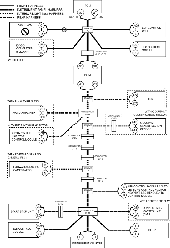
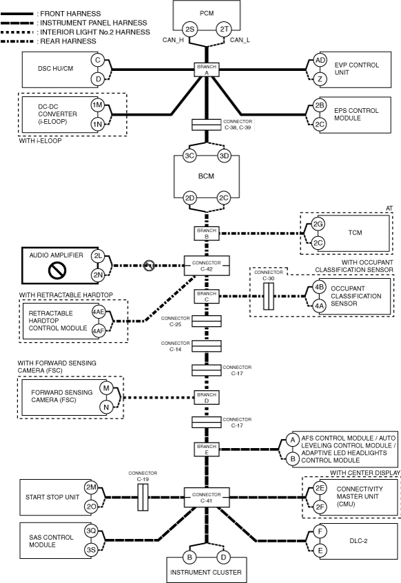
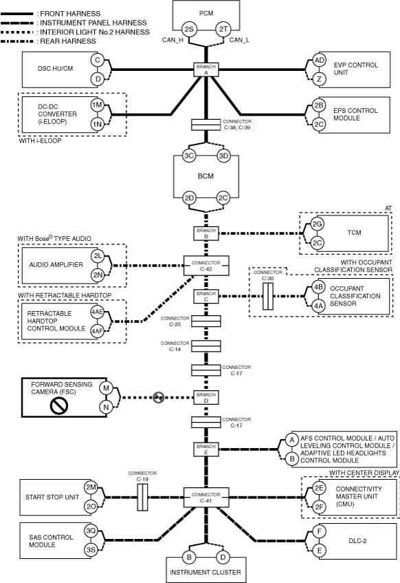
A
Possible cause
System wiring diagram
amxzzw00005586
|
Inspection item
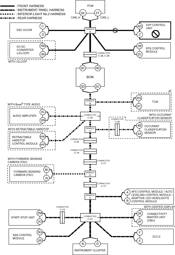
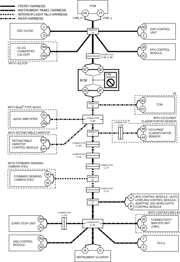
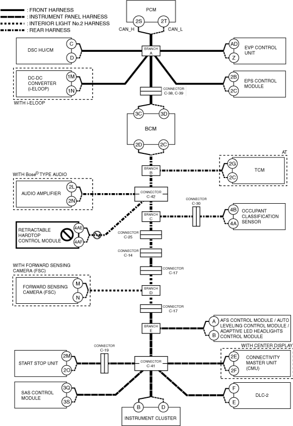
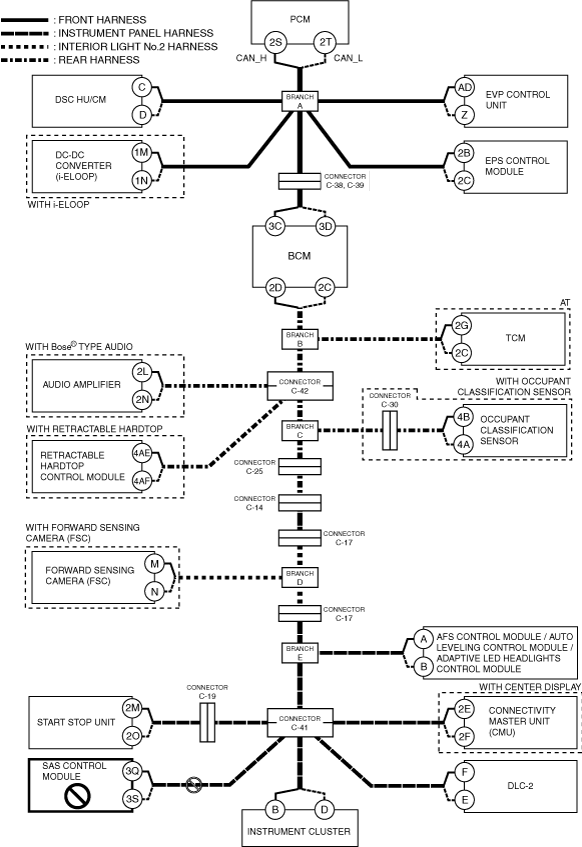
B
Possible cause
System wiring diagram
amxzzw00005587
|
Inspection item
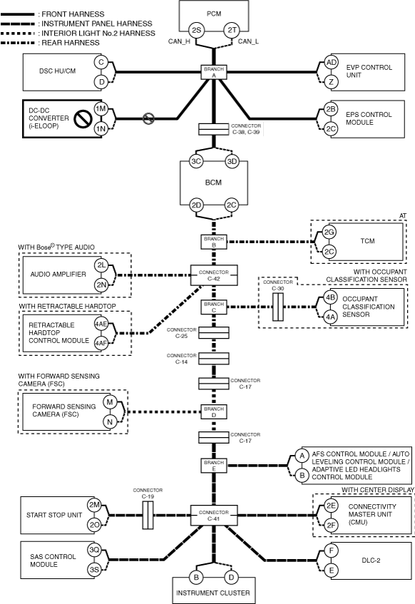
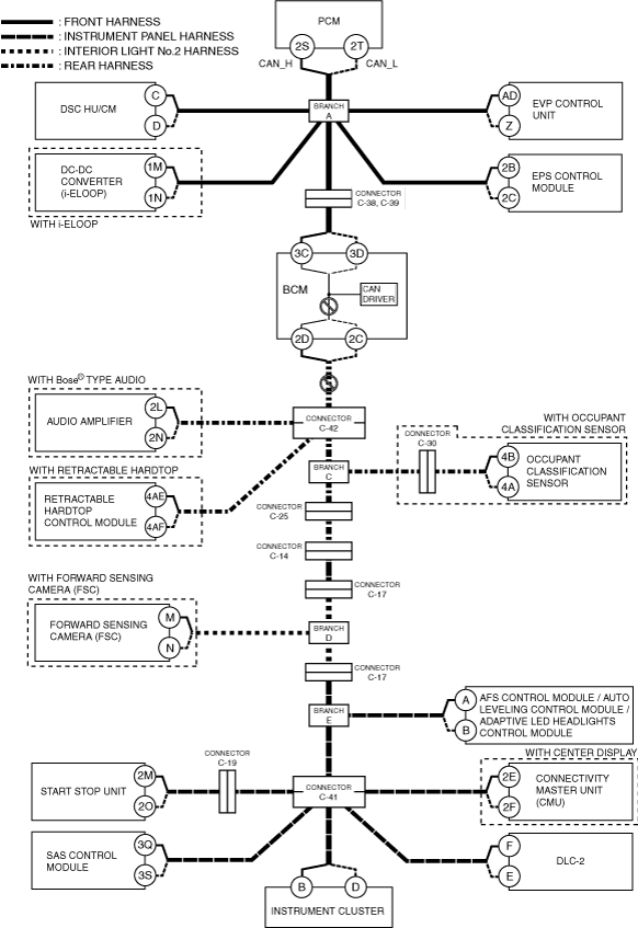
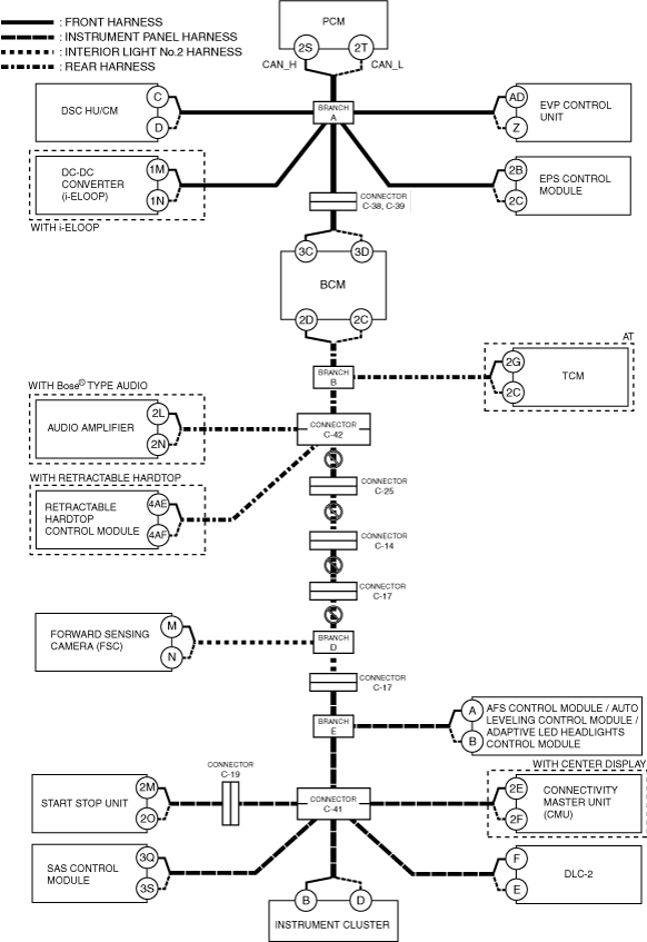
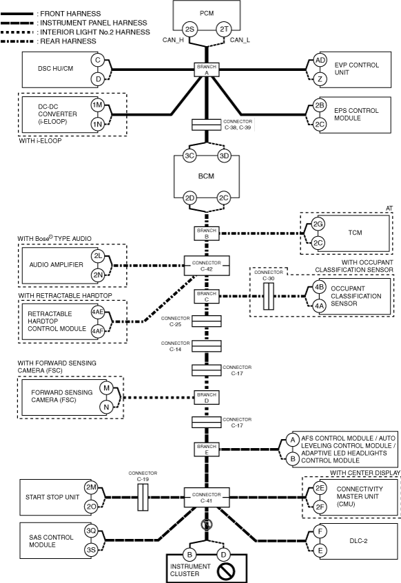
C
Possible cause
System wiring diagram
amxzzw00005588
|
Inspection item
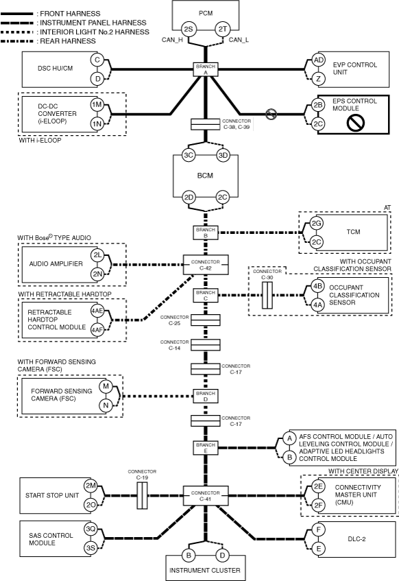
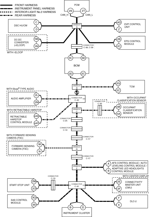
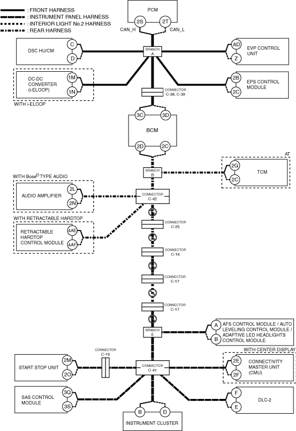
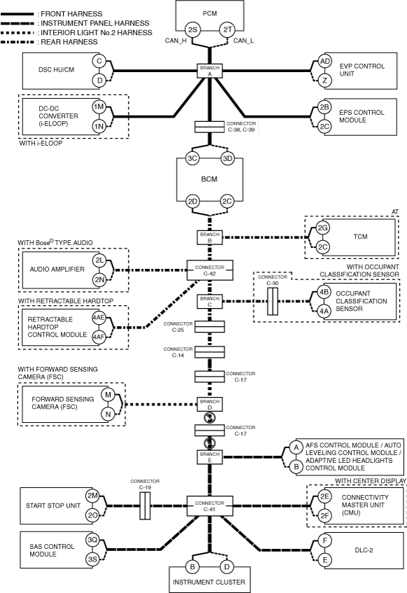
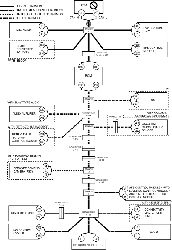
D
Possible cause
System wiring diagram
amxzzw00005589
|
Inspection item
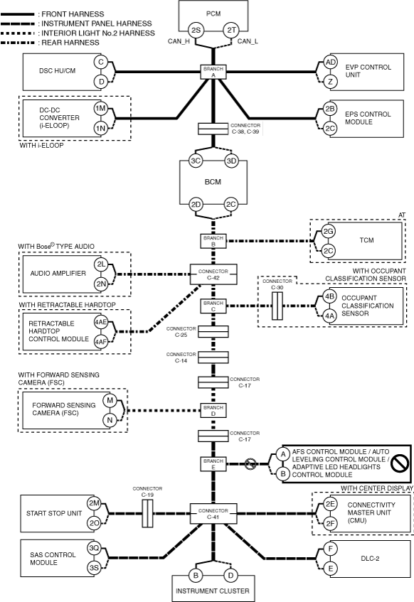
E
Possible cause
System wiring diagram
amxzzw00005590
|
Inspection item
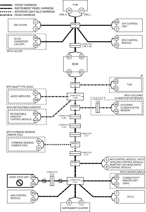
F
Possible cause
System wiring diagram
amxzzw00005591
|
Inspection item
G
Possible cause
System wiring diagram
amxzzw00005592
|
Inspection item
H
AT
System wiring diagram
amxzzw00005593
|
MT
System wiring diagram
amxzzw00005594
|
I
Possible cause
System wiring diagram
amxzzw00005595
|
Inspection item
J
Possible cause
System wiring diagram
amxzzw00005596
|
Inspection item
K
Possible cause
System wiring diagram
amxzzw00005597
|
Inspection item
L
Possible cause
System wiring diagram
amxzzw00005598
|
Inspection item
M
With occupant classification sensor
System wiring diagram
amxzzw00005599
|
Without occupant classification sensor and with forward sensing camera (FSC)
System wiring diagram
amxzzw00005600
|
Without occupant classification sensor and without forward sensing camera (FSC)
System wiring diagram
amxzzw00005601
|
N
Possible cause
System wiring diagram
amxzzw00005602
|
Inspection item
O
Possible cause
System wiring diagram
amxzzw00005603
|
Inspection item
P
Possible cause
System wiring diagram
amxzzw00005604
|
Inspection item
Q
Possible cause
System wiring diagram
amxzzw00005605
|
Inspection item
R
Possible cause
System wiring diagram
amxzzw00005606
|
Inspection item
S
Possible cause
System wiring diagram
amxzzw00005607
|
Inspection item
T
Possible cause
System wiring diagram
amxzzw00005608
|
Inspection item
U
Possible cause
System wiring diagram
amxzzw00005609
|
Inspection item