amxzzw00002994
|
GENERATOR REMOVAL/INSTALLATION [WITH i-ELOOP (SKYACTIV-G 1.5, SKYACTIV-G 2.0)]
id1317040030r2
Procedure Before i-ELOOP-Related Part Servicing
1. Disconnect the negative battery cable. (See NEGATIVE BATTERY TERMINAL DISCONNECTION/CONNECTION.)
2. Disconnect the service plug. (See SERVICE PLUG DISCONNECTION/CONNECTION [i-ELOOP].)
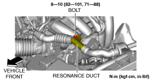
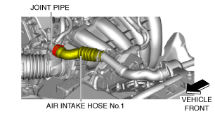
3. Set the resonance duct and air intake hoses No.1 and 2 aside as a single unit using the following procedure. (With resonance chamber No.2)
amxzzw00002994
|
amxzzw00002995
|
amxzzw00002996
|
4. Remove the battery and battery tray. (See BATTERY REMOVAL/INSTALLATION [SKYACTIV-G 1.5, SKYACTIV-G 2.0].)
5. Remove the air cleaner, air hose and resonance chamber No.1 as a single unit. (See INTAKE-AIR SYSTEM REMOVAL/INSTALLATION [SKYACTIV-G 1.5, SKYACTIV-G 2.0].)
6. Remove the generator drive belt. (See DRIVE BELT REMOVAL/INSTALLATION [SKYACTIV-G 1.5, SKYACTIV-G 2.0].)
7. Remove the drive belt auto tensioner. (See DRIVE BELT AUTO TENSIONER REMOVAL/INSTALLATION [SKYACTIV-G 1.5, SKYACTIV-G 2.0].)
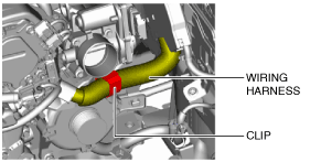
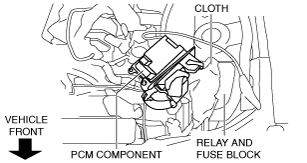
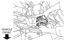
8. Detach the clip and set the wiring harness aside.
amxuuw00004275
|
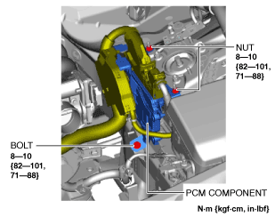
9. Remove the bolt and nuts shown in the figure.
amxzzw00002997
|
Example of PCM component movement
amxuuw00004277
|
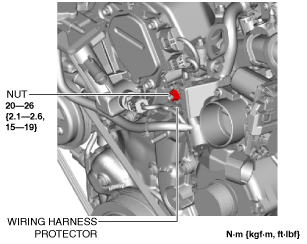
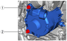
10. Remove the nut shown in the figure.
amxuuw00004278
|
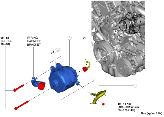
11. Remove in the order indicated in the table.
12. Install in the reverse order of removal.
amxuuw00004279
|
|
1
|
Terminal B cable
|
|
2
|
Generator connector
|
|
3
|
Generator
(See Generator Removal Note.)
(See Generator Installation Note.)
|
Generator Removal Note
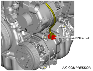
1. Disconnect the A/C compressor connector.
amxuuw00004280
|
2. Remove the generator upper bolt.
3. Remove the wiring harness bracket.
4. Remove the generator lower bolt.
5. Remove the generator.
amxuuw00004281
|
Generator Installation Note
1. To facilitate the installation of the generator to the engine, grasp the spacer in the bolt installation hole using pliers and push it down to the nut side.
ac5wzw00002650
|
2. Align the generator bolt installation holes on the engine and generator sides.
3. Set the wiring harness bracket to the installation position.
4. Temporarily tighten the generator bolts (upper and lower).
5. Tighten the generator bolts in the order shown in the figure.
amxuuw00004282
|
6. Connect the A/C compressor connector.
amxuuw00004280
|