 |
bsj6za00000622
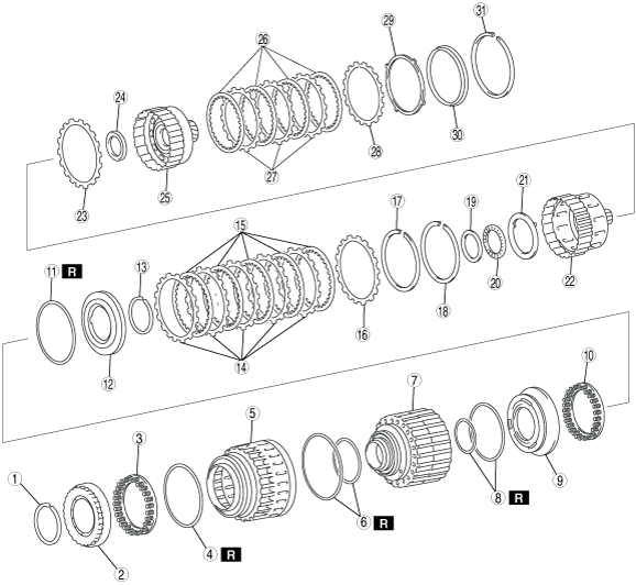
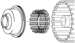
CLUTCH DRUM COMPONENT AND F4 ONE-WAY CLUTCH COMPONENT ASSEMBLY
id051300260800
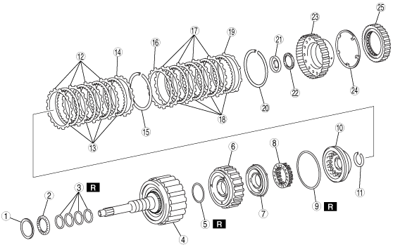
Components
bsj6za00000622
|
|
1
|
Bearing race
|
|
2
|
Thrust needle spring
|
|
3
|
Seal ring
|
|
4
|
Input shaft component
|
|
5
|
O-ring
|
|
6
|
C1 clutch position
|
|
7
|
C4 clutch position
|
|
8
|
Piston return spring
|
|
9
|
O-ring
|
|
10
|
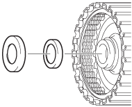
C1 clutch seal plate
|
|
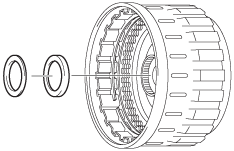
11
|
Snap ring
|
|
12
|
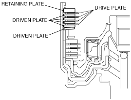
Driven plate
|
|
13
|
Drive plate
|
|
14
|
Retaining plate
|
|
15
|
Snap ring
|
|
16
|
Driven plate
|
|
17
|
Driven plate
|
|
18
|
Drive plate
|
|
19
|
Retaining plate
|
|
20
|
Snap ring
|
|
21
|
Bearing race
|
|
22
|
Thrust needle bearing
|
|
23
|
Clutch hub
|
|
24
|
Thrust washer
|
|
25
|
F4 one-way clutch
|
bsj6za00000623
|
|
1
|
Snap ring
|
|
2
|
C3 clutch seal plate
|
|
3
|
Piston return spring
|
|
4
|
O-ring
|
|
5
|
C3 clutch piston component
|
|
6
|
O-ring
|
|
7
|
C2, C3 clutch drum
|
|
8
|
O-ring
|
|
9
|
C2 clutch piston
|
|
10
|
C2 clutch piston return spring
|
|
11
|
O-ring
|
|
12
|
C2 clutch seal plate
|
|
13
|
Snap ring
|
|
14
|
Driven plate
|
|
15
|
Drive plate
|
|
16
|
Retaining plate
|
|
17
|
Snap ring
|
|
18
|
Snap ring
|
|
19
|
Bearing race
|
|
20
|
Thrust bearing
|
|
21
|
Thrust washer
|
|
22
|
Clutch hub
|
|
23
|
Retaining plate
|
|
24
|
Thrust needle bearing
|
|
25
|
Clutch hub component
|
|
26
|
Drive plate
|
|
27
|
Driven plate
|
|
28
|
Retaining plate
|
|
29
|
Driven plate
|
|
30
|
Sleeve
|
|
31
|
Snap ring
|
Assembly Procedure
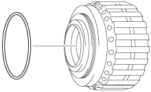
1. Apply ATF to the new O-rings.
2. Install the O-rings to the C2, C3 clutch drum.
bsj6za00000243
|
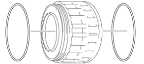
3. Apply ATF to the new O-rings.
4. Install the O-rings to the C3 clutch piston component.
bsj6za00000559
|
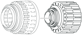
5. Apply ATF to the C2, C3 clutch drum and the C3 clutch piston component.
6. Install the C2, C3 clutch drum to the C3 clutch piston component.
bsj6za00000883
|
7. Apply ATF to the seal plate and the piston return spring.
8. Install the seal plate and the piston return spring to the C3 clutch hub component.
bsj6za00000561
|
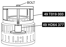
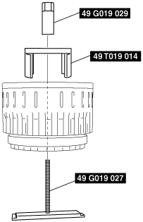
9. Install the SST using a M10-1.25 bolt with a length of 100 mm as shown in the figure to compress the piston return spring.
bsj6za00000815
|
10. Remove the snap ring using snap ring pliers.
bsj6za00000789
|
11. Apply ATF to the new O-rings.
12. Install the O-rings to the C2 clutch piston.
bsj6za00000562
|
13. Apply ATF to the new O-rings.
14. Install the O-rings to the C2 clutch seal plate.
bsj6za00000181
|
15. Apply ATF to the C2 clutch piston and the C2, C3 clutch drum.
16. Install the C2 clutch piston and the C2, C3 clutch drum.
bsj6za00000563
|
17. Apply ATF to the C2 clutch seal plate and the C2, C3 clutch drum.
18. Install the C2 clutch seal plate and the C2 clutch piston return spring to the C2, C3 clutch drum.
bsj6za00000566
|
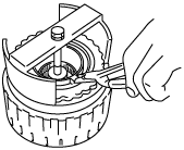
19. Install the SST as shown in the figure, and compress the C2 clutch piston return spring.
bsj6za00000875
|
20. Install the snap ring using snap ring pliers.
bsj6za00000787
|
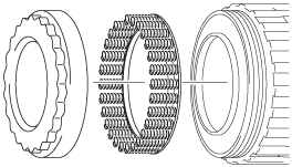
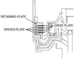
21. Apply ATF to the driven plate (C2) and the drive plate (C2) and the retaining plate (C2).
22. Install the driven plate (C2), the drive plate (C2), the retaining plate (C2) to the C2, C3 clutch drum.
bsj6za00000673
|
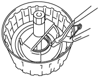
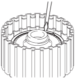
23. Using a flathead screwdriver, install the snap ring (C2) to the C2, C3 clutch drum.
bsj6za00000186
|
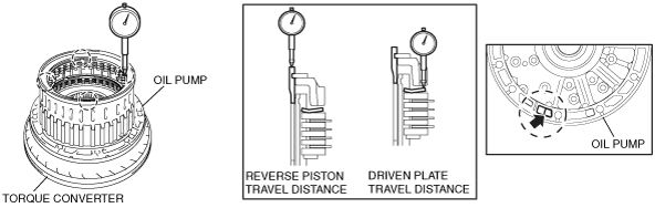
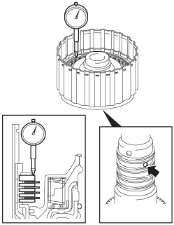
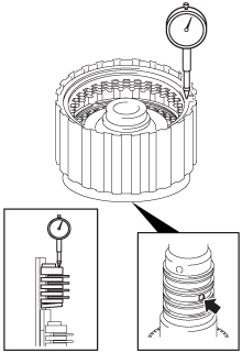
24. Measure the retaining plate travel distance at both ends across the diameter using a dial gauge while blowing compressed air into the oil passage as shown in the figure, and calculate the average value. Verify that the piston moves smoothly.
bsj6za00000884
|
|
Identification mark |
Thickness (mm {in}) |
|---|---|
|
0
|
2.95—3.05 {0.016—0.120}
|
|
1
|
3.05—3.15 {0.120—0.124}
|
|
2
|
3.15—3.25 {0.124—0.128}
|
|
3
|
3.25—3.35 {0.128—0.132}
|
|
4
|
3.35—3.45 {0.132—0.136}
|
|
5
|
3.45—3.55 {0.136—0.140}
|
|
6
|
3.55—3.65 {0.140—0.144}
|
|
7
|
3.65—3.75 {0.144—0.148}
|
|
8
|
3.75—3.85 {0.148—0.152}
|
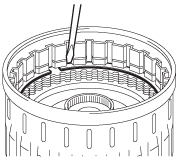
25. Using a flathead screwdriver, install the snap ring (C3) to the C2, C3 clutch drum.
bsj6za00000188
|
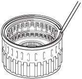
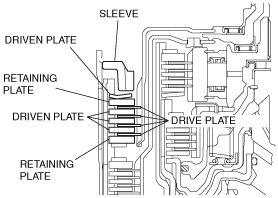
26. Apply ATF to the retaining plate (C3), the driven plate (C3), the drive plate (C3).
27. Install the retaining plate (C3) and the driven plate (C3) and the drive plate (C3) and the sleeve to the C2, C3 clutch drum.
bsj6za00000674
|
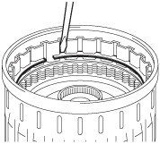
28. Using a flathead screwdriver, install the snap ring (C3) to the C2, C3 clutch drum.
bsj6za00000190
|
29. Measure the driven plate travel distance of the reverse piston travel distance and driven plate at the both ends across the diameter using a dial gauge while blowing compressed air into the oil passage as shown in the figure, and calculate the average value. Verify that the piston moves smoothly.
bsj6za00000885
|
|
Identification mark |
Thickness (mm {in}) |
|---|---|
|
0
|
2.35—2.45 {0.093—0.096}
|
|
1
|
2.45—2.55 {0.096—0.100}
|
|
2
|
2.55—2.65 {0.100—0.104}
|
|
3
|
2.65—2.75 {0.104—0.108}
|
|
4
|
2.75—2.85 {0.108—0.112}
|
|
5
|
2.85—2.95 {0.112—0.116}
|
|
6
|
2.95—3.05 {0.116—0.120}
|
|
7
|
3.05—3.15 {0.120—0.124}
|
|
8
|
3.15—3.25 {0.124—0.128}
|
|
9
|
3.25—3.35 {0.128—0.132}
|
|
A
|
3.35—3.45 {0.132—0.136}
|
|
B
|
3.45—3.55 {0.136—0.140}
|
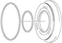
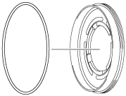
30. Apply ATF to the sliding surface of the new seal ring input shaft.
31. Compress the seal rings as shown in the figure and install them to the input shaft component.
bsj6za00000675
|
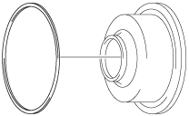
32. Apply ATF to the new D-ring.
33. Install the D-ring to the C4 clutch seal plate.
bsj6za00000567
|
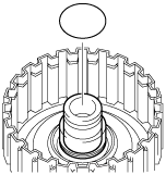
34. Apply ATF to the new O-ring.
35. Install the O-ring to the input shaft component.
bsj6za00000568
|
36. Apply ATF to the C1 clutch piston and the C4 clutch piston to the input shaft component.
37. Install the C1 clutch piston and the C4 clutch piston to the input shaft component.
bsj6za00000569
|
38. Apply ATF to the C1 clutch seal plate and the input shaft component.
39. Install the C1 clutch seal plate and the piston return spring to the input shaft component.
bsj6za00000676
|
40. Place the SST on the C1 clutch seal plate and compress the piston return spring with a press.
41. Install the snap ring using snap ring pliers.
bsj6za00000871
|
42. Apply ATF to the retaining plate (C4), the driven plate (C4), the drive plate (C4).
43. Install the retaining plate (C4), the driven plate (C4), the drive plate (C4) to the input shaft component.
bsj6za00000677
|
44. Using a flathead screwdriver, install the snap ring to the input shaft component.
bsj6za00000199
|
45. Measure the retaining plate travel distance at both ends across the diameter using a dial gauge while blowing compressed air into the oil passage as shown in the figure, and calculate the average value. Verify that the piston moves smoothly.
bsj6za00000886
|
|
Identification mark |
Thickness (mm {in}) |
|---|---|
|
0
|
2.95—3.05 {0.116—0.120}
|
|
1
|
3.05—3.15 {0.120—0.124}
|
|
2
|
3.15—3.25 {0.124—0.128}
|
|
3
|
3.25—3.35 {0.128—0.132}
|
|
4
|
3.35—3.45 {0.132—0.136}
|
|
5
|
3.45—3.55 {0.136—0.140}
|
|
6
|
3.55—3.65 {0.140—0.144}
|
|
7
|
3.65—3.75 {0.144—0.148}
|
|
8
|
3.75—3.85 {0.148—0.152}
|
|
9
|
3.85—3.95 {0.152—0.156}
|
46. Apply ATF to the retaining plate (C1), the driven plate (C1), the drive plate (C1).
47. Install the retaining plate (C1), the driven plate (C1), the drive plate (C1) to the input shaft component.
bsj6za00000678
|
48. Using a flathead screwdriver, install the snap ring to the input shaft component.
bsj6za00000202
|
49. Measure the retaining plate travel distance at both ends across the diameter using a dial gauge while blowing compressed air into the oil passage as shown in the figure, and calculate the average value. Verify that the piston moves smoothly.
bsj6za00000887
|
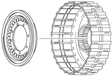
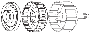
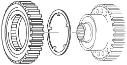
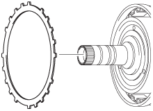
50. Apply ATF to the F4 one-way clutch and the thrust washer.
51. Install the F4 one-way clutch to the clutch hub.
bsj6za00000204
|
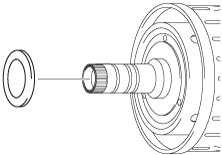
52. Apply ATF to the bearing race.
53. Install the bearing race to the C1, C4 clutch component.
bsj6za00000205
|
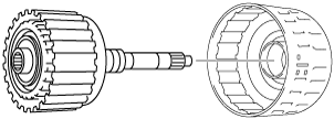
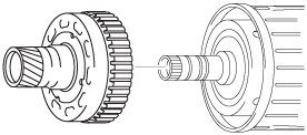
54. Install the clutch hub to the C1, C4 clutch component.
bsj6za00000679
|
55. Apply ATF to the bearing race.
56. Install the bearing race to the C3 clutch piston component.
bsj6za00000207
|
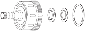
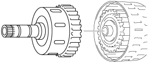
57. Install the C1, C4 clutch component to the C2, C3 clutch drum.
bsj6za00000594
|
58. Apply ATF to the thrust bearing, the bearing race and the thrust washer.
59. Install the thrust bearing, bearing race and thrust washer.
bsj6za00000209
|
60. Install the clutch hub to the C3 clutch piston component.
bsj6za00000818
|
61. Apply ATF to the thrust needle spring.
62. Install the thrust needle spring to the clutch hub.
bsj6za00000211
|
63. Apply ATF to the retaining plate.
64. Install the retaining plate to the C3 clutch piston component.
bsj6za00000571
|
65. Install the clutch hub component to the C3 clutch piston component.
bsj6za00000819
|
66. Apply ATF to the retaining plate, the drive plate, the driven plate.
67. Install the retaining plate (C3), the drive plate (C3), and the driven plate (C3) to the clutch hub component.
bsj6za00000682
|
68. Using a flathead screwdriver, install the snap ring to the C3 clutch piston component.
bsj6za00000820
|