 |
bsj6za00000856
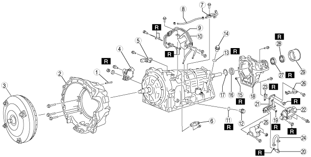
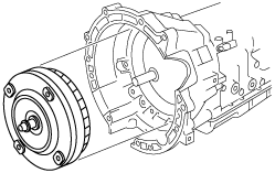
AUTOMATIC TRANSMISSION ASSEMBLY
id051300261900
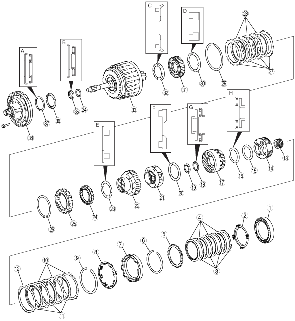
Assembly
Bearing and race locations
bsj6za00000856
|
|
1
|
B2 brake piston component
|
|
2
|
Piston return spring
|
|
3
|
Driven plate
|
|
4
|
Drive plate
|
|
5
|
Retaining plate
|
|
6
|
Snap ring
|
|
7
|
B1 brake piston component
|
|
8
|
Piston return spring
|
|
9
|
Snap ring
|
|
10
|
Driven plate
|
|
11
|
Drive plate
|
|
12
|
Retaining plate
|
|
13
|
Sun gear
|
|
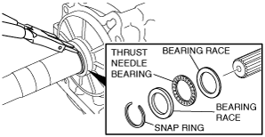
14
|
Middle planetary gear component
|
|
15
|
Bearing race
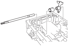
|
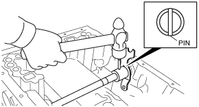
|
16
|
Thrust needle bearing
|
|
17
|
Front and middle ring gear component
|
|
18
|
Thrust needle bearing
|
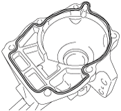
|
19
|
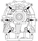
Bearing race
|
|
20
|
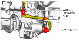
Thrust washer
|
|
21
|
Front planetary gear component
|
|
22
|
Bearing race
|
|
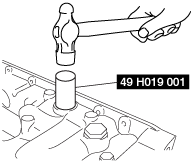
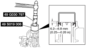
23
|
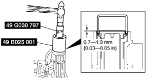
Thrust washer
|
|
24
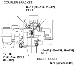
|
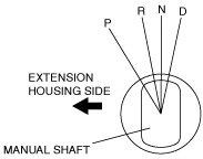
F1 one-way clutch
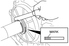
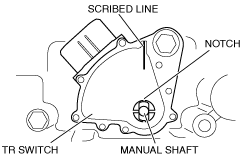
|
|
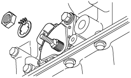
25
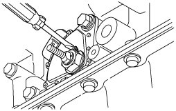
|
B3 brake piston component
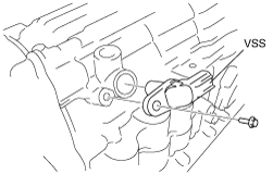
|
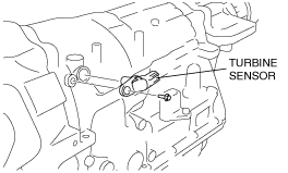
|
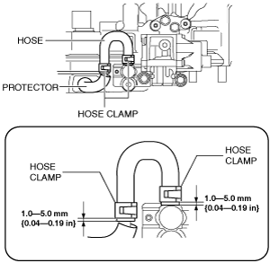
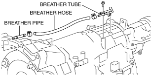
26
|
Snap ring
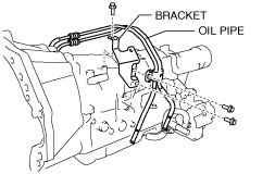
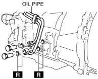
|
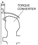
|
27
|
Driven plate
|
|
28
|
Drive plate
|
|
29
|
Snap ring
|
|
30
|
Thrust washer
|
|
31
|
F2 one-way clutch
|
|
32
|
Thrust washer
|
|
33
|
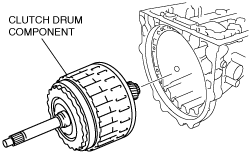
Clutch drum component
|
|
34
|
Thrust needle bearing
|
|
35
|
Bearing race
|
|
36
|
Thrust needle bearing
|
|
37
|
Bearing race
|
|
38
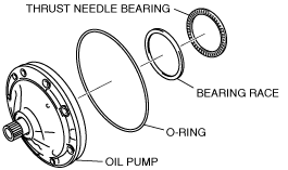
|
Oil pump
|
bsj6za00000504
|
|
1
|
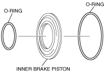
O-ring
|
|
2
|
O-ring
|
|
3
|
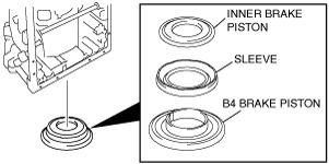
Inner brake piston
|
|
4
|
O-ring
|
|
5
|
O-ring
|
|
6
|
Sleeve
|
|
7
|
O-ring
|
|
8
|
B4 brake piston
|
|
9
|
Piston return spring
|
|
10
|
Snap ring
|
|
11
|
Brake tube
|
|
12
|
Thrust needle bearing
|
|
13
|
Bearing race
|
|
14
|
Rear planetary gear component
|
|
15
|
Driven plate
|
|
16
|
Drive plate
|
|
17
|
Driven plate
|
|
18
|
Retaining plate
|
|
19
|
Intermediate shaft
|
|
20
|
Bearing race
|
|
21
|
Needle bearing
|
|
22
|
Bearing race
|
|
23
|
Rear ring gear component
|
|
24
|
F3 one-way clutch
|
|
25
|
Inner race
|
|
26
|
Snap ring
|
|
27
|
Stopper spring
|
|
28
|
Bearing race
|
|
29
|
Thrust needle bearing
|
|
30
|
Bearing race
|
|
31
|
Snap ring
|
|
|
|
A |
B |
C |
D |
E |
F |
G |
H |
I |
J |
K |
|---|---|---|---|---|---|---|---|---|---|---|---|---|
|
Bearing race (Front) (mm)
|
Outer diameter
|
87.74
{3.45}
|
35.6
{1.40}
|
92.6
{3.65}
|
102.7
{4.04}
|
96.7
{3.81}
|
83.6
{3.29}
|
50.8
{1.20}
|
-
|
44.9
{1.77}
|
56.7
{2.23}
|
51.2
{2.02}
|
|
Inner diameter
|
74.2
{2.92}
|
20.00
{0.79}
|
63.8
{2.51}
|
89.3
{3.52}
|
76.3
{3.00}
|
60.0
{2.36}
|
34.9
{1.37}
|
-
|
29.6
{1.06}
|
43.3
{1.70}
|
37.0
{1.46}
|
|
|
Bearing (mm)
|
Outer diameter
|
85.6
{3.37}
|
41.0
{1.61}
|
-
|
-
|
-
|
-
|
53.1
{2.09}
|
73.5
{2.89}
|
43.85
{1.73}
|
58.0
{2.28}
|
52.5
{2.07}
|
|
Inner diameter
|
71.9
{2.83}
|
20.0
{0.79}
|
-
|
-
|
-
|
-
|
38.6
{1.52}
|
58.5
{2.30}
|
27.8
{1.09}
|
40.6
{1.60}
|
36.1
{1.42}
|
|
|
Bearing race (Rear) (mm)
|
Outer diameter
|
-
|
-
|
-
|
-
|
-
|
-
|
-
|
71.2
{2.80}
|
43.7
{1.72}
|
-
|
51.0
{2.01}
|
|
Inner diameter
|
-
|
-
|
-
|
-
|
-
|
-
|
-
|
54.8
{2.16}
|
27.8
{1.09}
|
-
|
36.1
{1.42}
|
Components
bsj7ja00000009
|
|
1
|
Breather pipe
|
|
2
|
Converter housing
|
|
3
|
Torque converter
|
|
4
|
TR switch
|
|
5
|
Turbine sensor
|
|
6
|
VSS
|
|
7
|
Breather tube
|
|
8
|
Breather hose
|
|
9
|
Bracket (MX-5 (ND))
|
|
10
|
Oil pipe (MX-5 (ND))
|
|
11
|
O-ring
|
|
12
|
Check plug
|
|
13
|
O-ring
|
|
14
|
Filler plug
|
|
15
|
Oil seal (with i-stop)
|
|
16
|
Bearing (MX-5 (ND))
|
|
17
|
Snap ring (MX-5 (ND))
|
|
18
|
Extension housing
|
|
19
|
O-ring (with i-stop)
|
|
20
|
Elbow (with i-stop)
|
|
21
|
Spacer (with i-stop)
|
|
22
|
Electric AT oil pump (with i-stop)
|
|
23
|
Gasket (with i-stop)
|
|
24
|
Hose (with i-stop)
|
|
25
|
Under cover (with i-stop)
|
|
26
|
Coupler bracket (with i-stop)
|
|
27
|
Oil seal
|
|
28
|
Extension housing shroud
|
|
29
|
Extension dust deflector
|
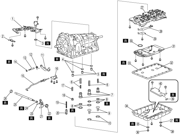
bsj7ja00000010
|
|
1
|
Coupler component
|
|
2
|
Clip
|
|
3
|
O-ring
|
|
4
|
Gasket
|
|
5
|
Gasket
|
|
6
|
Accumulator spring
|
|
7
|
Accumulator piston
|
|
8
|
O-ring
|
|
9
|
Spring
|
|
10
|
Snap ring
|
|
11
|
Parking pawl
|
|
12
|
Spring
|
|
13
|
Parking pawl shaft
|
|
14
|
Driven plate
|
|
15
|
Parking rod
|
|
16
|
Bracket
|
|
17
|
Spring
|
|
18
|
Accumulator valve
|
|
19
|
Spring
|
|
20
|
Check valve
|
|
21
|
Manual valve
|
|
22
|
Oil seal
|
|
23
|
Pin
|
|
24
|
Manual shaft washer
|
|
25
|
Manual shaft
|
|
26
|
Oil seal
|
|
27
|
Control valve body
|
|
28
|
Detent spring
|
|
29
|
Detent spring cover
|
|
30
|
O-ring
|
|
31
|
Oil strainer
|
|
32
|
Magnet
|
|
33
|
Oil pan gasket
|
|
34
|
Oil pan
|
|
35
|
Gasket
|
|
36
|
Overflow plug
|
|
37
|
Gasket
|
|
38
|
Drain plug
|
|
39
|
O-ring (with i-stop)
|
|
40
|
Oil strainer (electric AT oil pump) (with i-stop)
|
Disassembly Procedure
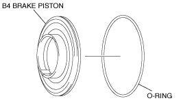
1. Apply ATF to the new O-ring.
2. Install the O-ring to the B4 brake piston.
bsj6za00000684
|
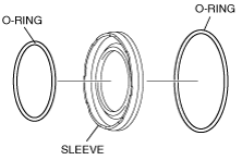
3. Apply ATF to the new O-rings.
4. Install the O-ring to the sleeve.
bsj6za00000685
|
5. Apply ATF to the new O-rings
6. Install the O-ring to the inner brake piston.
bsj6za00000686
|
7. Apply ATF to the sliding surface of the transmission case.
8. Install the inner brake piston, sleeve and B4 brake piston to the transmission case.
bsj6za00000687
|
9. Install the piston return spring.
bsj6za00000453
|
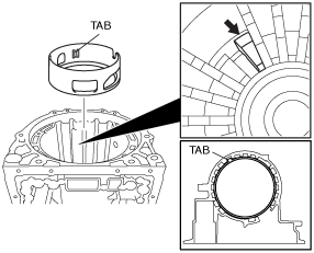
10. Using the SST, compress the piston return spring and install the snap ring into the groove.
bsj6za00000881
|
11. Install the brake tube to the transmission case as shown in the figure.
bsj6za00000688
|
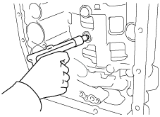
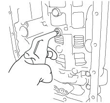
12. Verify that B4 brake piston moves smoothly when the compressed air atomization equipment lever is pulled/released while blowing compressed air into the transmission case.
bsj6za00000629
|
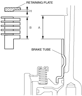
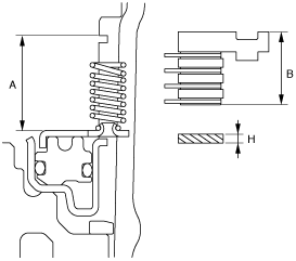
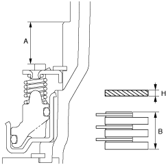
13. Measure the level difference (length A) between the brake tube upper surface and the retaining plate contact surface at the both ends across the B4 brake piston diameter using a vernier caliper, and calculate the average value.
bsj6za00000689
|
14. Measure the thickness of all the driven plates and drive plate components (5), and driven plates (4) at the both ends across the diameter using a vernier caliper, and calculate the average value.
15. Calculate the pack clearance using the following formula.
16. If the pack clearance exceeds the maximum specification, select the retaining plate with a clearance that is the maximum specification and install it.
Retaining plate thickness H (mm {in})
|
Identification mark |
Thickness (mm {in}) |
|---|---|
|
0
|
0
|
|
2
|
0.15—0.25 {0.006—0.010}
|
|
4
|
0.35—0.45 {0.014—0.0177}
|
|
6
|
0.55—0.65 {0.022—0.026}
|
|
8
|
0.75—0.85 {0.030—0.033}
|
|
10
|
0.95—1.05 {0.037—0.041}
|
|
12
|
1.15—1.25 {0.045—0.049}
|
|
14
|
1.35—1.45 {0.054—0.057}
|
17. Apply ATF to the bearing race, thrust needle bearing and install to the rear planetary gear component.
bsj6za00000690
|
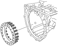
18. Install the rear planetary gear component to the transmission case.
bsj6za00000691
|
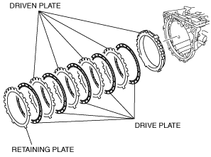
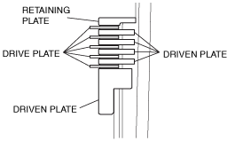
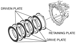
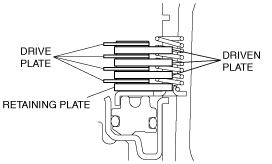
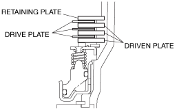
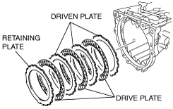
19. Install the retaining plates, drive plates and driven plates to the transmission case as shown in the figure.
bsj6za00000692
|
20. Install the retaining plate, drive plates and driven plates in the order indicated in the figure.
bsj6za00000693
|
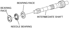
21. Apply ATF to the bearing race, needle bearing race and install to the intermediate shaft.
bsj6za00000694
|
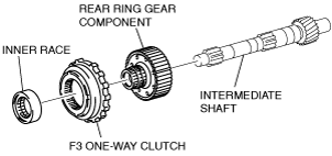
22. Install the rear ring gear component, F3 one-way clutch and inner race to the intermediate shaft.
bsj6za00000695
|
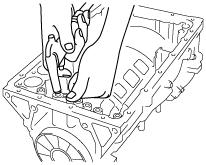
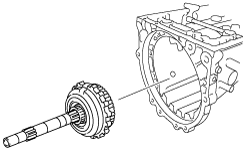
23. Install the intermediate shaft component to the transmission case.
bsj6za00000428
|
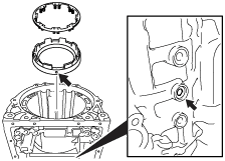
24. Verify that the snap ring is correctly positioned.
bsj6za00000458
|
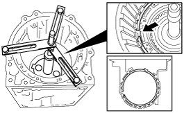
25. Install snap ring to the transmission case using snap ring pliers.
bsj6za00000427
|
26. Install the stopper spring to the transmission case.
bsj6za00000426
|
27. Install the brake piston and brake cylinder to the transmission case.
bsj6za00000490
|
28. Verify that B2 brake piston moves smoothly when the compressed air atomization equipment lever is pulled/released while blowing compressed air into the transmission case.
bsj6za00000491
|
29. Measure the level difference (length A) between the brake piston upper surface and the snap ring contact surface at the both ends across the brake piston diameter using a vernier caliper, and calculate the average value.
bsj6za00000492
|
30. Measure the thickness of all the driven plates and drive plate components (4), and driven plates (3) at the both ends across the diameter using a vernier caliper, and calculate the average value.
31. Calculate the pack clearance using the following formula.
32. If the pack clearance exceeds the maximum specification, select the retaining plate with a clearance that is the maximum specification and install it.
Retaining plate thickness H (mm {in})
|
Identification mark |
Thickness (mm {in}) |
|---|---|
|
0
|
1.95—2.05 {0.077—0.081}
|
|
1
|
2.05—2.15 {0.081—0.085}
|
|
2
|
2.15—2.25 {0.085—0.089}
|
|
3
|
2.25—2.35 {0.089—0.093}
|
|
4
|
2.35—2.45 {0.093—0.096}
|
|
5
|
2.45—2.55 {0.096—0.100}
|
|
6
|
2.55—2.65 {0.100—0.104}
|
|
7
|
2.65—2.75 {0.104—0.108}
|
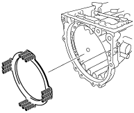
33. Install the return spring to the transmission case.
bsj6za00000423
|
34. Install the retaining plate, drive plate and driven plates to the transmission case as shown in the figure.
bsj6za00000696
|
35. Install the retaining plate, drive plate component, and driven plates in the order indicated in the figure.
bsj6za00000697
|
36. Install the retaining plate to the transmission case.
bsj6za00000472
|
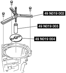
37. Install the SST as shown in the figure, and compress the piston return spring.
bsj6za00000826
|
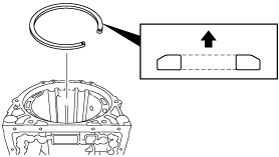
38. Using a flathead screwdriver, install the snap ring into the groove.
bsj6za00000782
|
39. Install the B1 brake piston component and return spring to the transmission case as shown in the figure.
bsj6za00000495
|
40. Install the SST as shown in the figure, and compress the piston return spring.
bsj6za00000827
|
41. Using a flathead screwdriver, install the snap ring to the transmission case.
bsj6za00000784
|
42. Verify that B1 brake piston moves smoothly when the compressed air atomization equipment lever is pulled/released while blowing compressed air into the transmission case.
bsj6za00000497
|
43. Measure the level difference (length A) between the B1 brake piston upper surface and retaining plate contact surface at the both ends across the B1 brake piston diameter using a vernier caliper, and calculate the average value.
bsj6za00000498
|
44. Measure the thickness of all the driven plates and drive plate components (3), and driven plates (3) at the both ends across the diameter using a vernier caliper, and calculate the average value.
45. Calculate the pack clearance using the following formula.
46. If the pack clearance exceeds the maximum specification, select the retaining plate with a clearance that is the maximum specification and install it.
Retaining plate thickness H (mm {in})
|
Identification mark |
Thickness (mm {in}) |
|---|---|
|
0
|
1.95—2.05 {0.077—0.081}
|
|
1
|
2.15—2.25 {0.085—0.089}
|
|
2
|
2.35—2.45 {0.093—0.096}
|
|
3
|
2.55—2.65 {0.100—0.104}
|
47. Install the drive plate, driven plates and retaining plate to the transmission component as shown in the figure.
bsj6za00000700
|
48. Install the driven plates, drive plate, and the retaining plate in the order indicated in the figure.
bsj6za00000701
|
49. Install the bearing race and thrust needle bearing to the middle planetary gear component.
50. Install the middle planetary gear component and sun gear.
bsj6za00000702
|
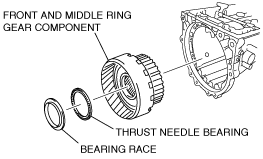
51. Apply ATF to the bearing race and thrust needle bearing.
52. Install the bearing race and thrust needle bearing to the middle planetary gear component.
53. Install the front and middle planetary gear ring component.
bsj6za00000703
|
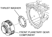
54. Apply ATF to the thrust washer.
55. Install the thrust washer to the front planetary gear component.
bsj6za00000704
|
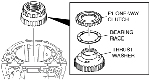
56. Apply ATF to the thrust washer and install it to the bearing race.
57. Install the F1 one-way clutch component to the bearing race.
bsj6za00000705
|
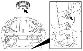
58. Install the brake piston to the transmission case as shown in the figure.
bsj6za00000501
|
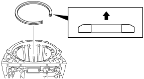
59. Verify that the snap ring is correctly positioned.
bsj6za00000502
|
60. Using snap ring pliers, install snap ring into the groove.
bsj6za00000463
|
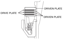
61. Install the drive plate and driven plate as shown in the figure.
bsj6za00000706
|
62. Install the driven plates, drive plate and the retaining plate in the order indicated in the figure.
bsj6za00000707
|
63. Using a flathead screwdriver, install the snap ring into the groove.
bsj6za00000407
|
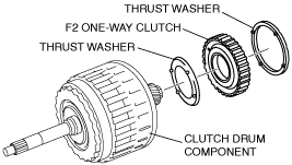
64. Apply ATF to the thrust washer and install it to the F2 one-way clutch component.
65. Install the F2 one-way clutch component to the clutch drum component.
bsj6za00000708
|
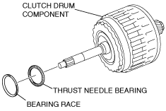
66. Apply ATF to the bearing race and thrust needle bearing.
67. Install the bearing race and thrust needle bearing to the clutch drum component and the F2 one-way clutch component.
bsj6za00000709
|
68. Install the clutch drum component and F2 one-way clutch component.
bsj6za00000710
|
69. Apply ATF to the new O-ring.
70. Install the O-ring to the oil pump component.
71. Apply ATF to the thrust needle bearing, bearing race and install it to the oil pump component.
bsj6za00000711
|
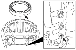
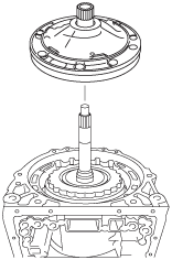
72. Install the oil pump as shown in the figure.
bsj6za00000507
|
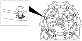
73. Install the bolt as shown in the figure.
bsj6za00000508
|
74. Apply ATF to the thrust needle bearing and the bearing race.
bsj6za00000712
|
75. Install the thrust needle bearing and bearing race to the front planetary gear component.
76. Install snap ring using snap ring pliers.
77. Measure the clearance between snap ring and bearing race using a thickness gauge.
bsj6za00000713
|
Retaining plate size
|
Identification mark |
Thickness (mm {in}) |
|---|---|
 |
3.80 {0.150}
|
 |
3.85 {0.152}
|
 |
3.90 {0.154}
|
 |
3.95 {0.156}
|
 |
4.00 {0.157}
|
 |
4.05 {0.159}
|
 |
4.10 {0.161}
|
 |
4.15 {0.163}
|
 |
4.20 {0.165}
|
 |
4.25 {0.167}
|
 |
4.30 {0.169}
|
 |
4.35 {0.171}
|
78. Verify that the input shaft turns smoothly.
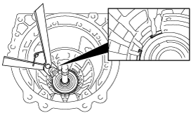
79. Using a dial indicator, measure the input shaft end play.
bsj6za00000481
|
80. Using the SST and a hammer, install a new oil seal.
bsj6za00000482
|
81. Install a new manual shaft washer to the manual valve.
bsj6za00000483
|
82. Insert the manual shaft into the transmission case and assemble it to the manual valve.
83. Tap in a new pin using a hammer.
bsj6za00000715
|
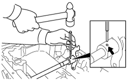
84. Align the manual shaft groove with the spacer hole and crimp them using a punch.
bsj6za00000868
|
85. Verify that the manual shaft turns smoothly.
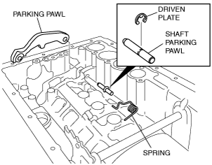
86. Install the parking pawl.
bsj6za00000716
|
87. Install the driven plate to the parking pawl shaft.
88. Install the parking pawl shaft, spring.
89. Connect the parking rod to the manual valve.
bsj6za00000442
|
90. Install the bracket.
bsj6za00000441
|
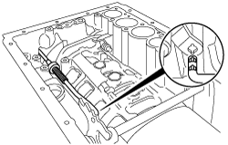
91. Set the manual valve to the P position and verify that the parking pawl shaft is properly engaged with the front planetary gear component.
bsj6za00000485
|
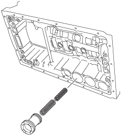
92. Install the accumulator valve and compression spring to the transmission case.
ardjjw00001277
|
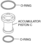
93. Apply ATF to the new O-ring and install the accumulator pistons C.
bsj6za00000717
|
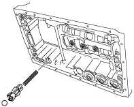
94. Install the accumulator piston C, compression spring to the transmission case.
ardjjw00001278
|
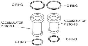
95. Apply ATF to the new O-ring and install the accumulator pistons A, B.
bsj6za00000718
|
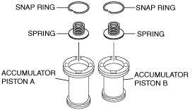
96. Using a flathead screwdriver, install the compression spring, snap ring to the accumulator pistons A, B.
bsj6za00000719
|
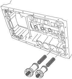
97. Install the accumulator pistons A, B and the compression spring to the transmission case.
ardjjw00001279
|
98. Apply ATF to the new transmission case gasket, new brake drum gasket and install the transmission case.
bsj6za00000039
|
99. Install the check valve subcomponent and compression spring to the transmission case.
bsj6za00000038
|
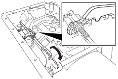
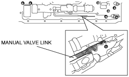
100. Connect the manual valve link, and install the control valve body component.
bsj6za00000720
|
ardjjw00001283
|
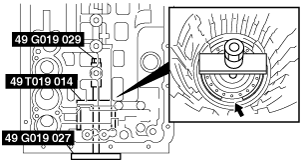
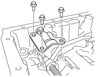
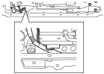
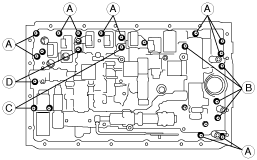
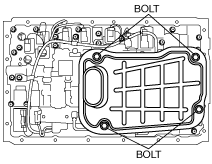
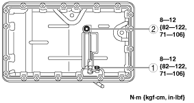
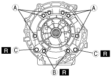
101. Temporarily tighten the bolts to the transmission case as shown in the figure.
bsj6za00000857
|
102. Tighten the bolts.
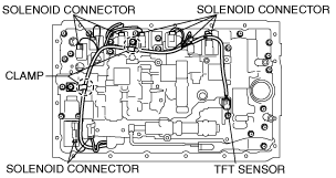
103. Install the detent spring cover and detent spring to the control valve body component.
104. Install the TFT sensor, lock plate to control valve body component.
105. Clamp the coupler component.
bsj6za00000721
|
106. Connect the solenoid connector to the solenoid.
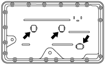
107. Apply ATF to the new O-ring and install the oil strainer.
108. Install the oil strainer to the control valve body component.
bsj6za00000722
|
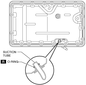
109. Clean the contact surface of the oil pan and transmission case.
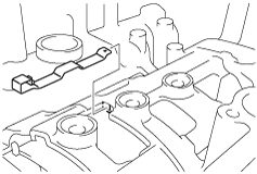
110. Install the magnet to the oil pan.
bsj6za00000901
|
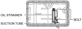
111. Install the O-ring and oil strainer (electric AT oil pump). (with i-stop)
amxzzw00003310
|
amxzzw00003311
|
amxzzw00003312
|
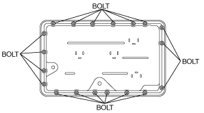
112. Install the new oil pan gasket and oil pan to the transmission case.
bsj6za00000723
|
113. Install the bolts to the transmission case.
114. Install the bearing, snap ring, and oil seal. (MX-5 (ND))
bsj6za00000899
|
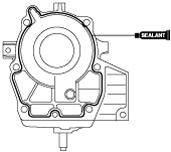
115. Remove the silicone sealant and be careful not to spill any oil on the contact surface of the transmission case and extension housing.
116. Clean the contact surface of the transmission case and the extension housing, and the bolt holes.
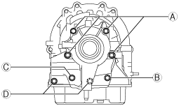
117. Install the extension housing. (MX-5 (ND))
bsj7ja00000012
|
bsj7ja00000013
|
|
Bolt number |
Bolt size |
Length (measured from below the head) (mm {in}} |
|---|---|---|
|
A
|
M10 -1.5
|
45 {1.8}
|
|
B
|
M10-1.5
|
40 {1.6}
|
|
C
|
M10-1.5
|
50 {2.0}
|
|
D
|
M8-1.25
|
35 {1.4}
|
118. Install the extension housing. (MX-5 (NC), RX-8 (SE))
bsj6za00000523
|
bsj6za00000524
|
|
Bolt number |
Bolt size |
Length (measured from below the head) (mm {in}} |
|---|---|---|
|
A
|
M10 -1.5
|
35 {1.38}
|
|
B
|
M10-1.5
|
45 {1.77}
|
119. .Assemble a new oil seal to the extension housing in the position shown in the figure using the SST and a hammer.
bsj6za00000858
|
120. Apply grease to the oil seal lip.
121. Using the SST and a hammer, install the new extension housing shroud to the extension housing as shown in the figure.
bsj6za00000859
|
122. Using a hammer and slab of wood, install the new extension dust deflector to the extension housing as shown in the figure.
bsj6za00000574
|
123. Temporarily tighten the bolts A and new bolts B, C by hand as shown in the figure.
bsj6za00000528
|
|
Bolt number |
Bolt size |
Length (measured from below the head) (mm {in}} |
|---|---|---|
|
A
|
M10 -1.5
|
35 {1.38}
|
|
B
|
M10-1.5
|
35 {1.38}
|
|
C
|
M10-1.75
|
38 {1.50}
|
124. Tighten the bolts.
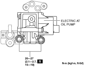
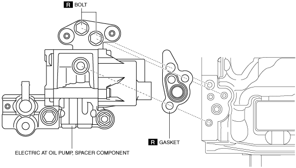
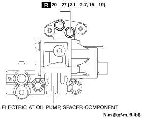
125. Install the electric AT oil pump. (with i-stop)
amxzzw00003301
|
amxzzw00003302
|
amxzzw00003303
|
amxzzw00003304
|
amxzzw00003305
|
amxzzw00003306
|
amxzzw00003307
|
amxzzw00003295
|
126. Turn the manual shaft fully to the extension housing side and turn it back two steps so that the N position is selected.
bsj6za00000726
|
127. Install the TR switch and temporarily tighten the new TR switch installation bolt.
128. Verify that the scribed line on the TR switch and the manual shaft notch are aligned.
bsj6za00000727
|
129. Install the lock washer and nut.
bsj6za00000903
|
130. Using a flathead screwdriver, bend the tab of lock washer.
bsj6za00000022
|
131. Tighten the TR switch installation bolt.
132. Install the VSS.
bsj6za00000728
|
133. Install the turbine sensor.
bsj6za00000729
|
134. Install the breather tube.
bsj8ua00000002
|
135. Install the breather pipe.
136. Install the breather hose.
137. Install the bracket and oil pipe. (MX-5 (ND))
LH
bsj8ua00000003
|
RH
bsj8ua00000004
|
138. Using a flathead screwdriver, position the drive gear on the oil pump component in the center. Then install the torque converter component to the transmission.
bsj6za00000020
|
139. To ensure that the torque converter is installed accurately, measure distance A between the end of the torque converter and the end of the converter housing.
bsj6za00000731
|
140. Clean the drain plug.
bsj6za00000890
|
141. Install the new drain plug gasket and drain plug to the oil pan.