|
bmm8um00000021
MAINSHAFT AND COUNTERSHAFT PARTS ASSEMBLY
id051100010800
1. Assemble using the procedure shown in the figure.
bmm8um00000021
|
|
1
|
Countershaft
|
|
2
|
Countershaft front bearing
|
|
3
|
Snap ring
|
|
4
|
Main shaft gear component
|
|
5
|
6th synchronizer ring
|
|
6
|
Bearing
|
|
7
|
Main drive gear
|
|
8
|
Bearing housing component
|
|
9
|
Counter 4th gear
|
|
10
|
Washer
|
|
11
|
Gear sleeve
|
|
12
|
Friction damper
|
|
13
|
4th gear
|
|
14
|
4th synchronizer component
|
|
15
|
3rd/4th clutch hub
|
|
16
|
Synchronizer key
|
|
17
|
3rd/4th clutch hub sleeve
|
|
18
|
Synchronizer key spring
|
|
19
|
3rd/4th clutch hub component
|
|
20
|
Locknut (main shaft)
|
|
21
|
3rd synchronizer component
|
|
22
|
3rd gear
|
|
23
|
Steel ball
|
|
24
|
Washer
(See Washer Assembly Note.)
|
|
25
|
Snap ring
|
|
26
|
Spacer
|
|
27
|
Counter 3rd gear
|
|
28
|
Countershaft rear bearing
|
|
29
|
Counter reverse gear
|
|
30
|
Locknut (countershaft)
|
|
31
|
Main shaft rear bearing
|
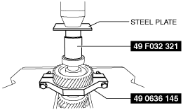
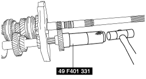
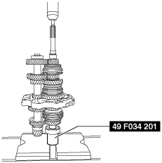
Countershaft Front Bearing Assembly Note
1. Assemble the countershaft front bearing using the SST and the press.
bmm8um00000022
|
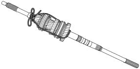
Bearing Housing Component Assembly Note
1. Assemble the 6th synchronizer ring, bearing, and main drive gear to the main shaft gear component and secure them using a rope.
bmm6jm00000064
|
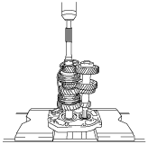
2. Set the bearing housing component, main shaft gear component, and countershaft to the press.
3. While gradually pressing the main shaft using a press, lightly tap the countershaft using a plastic hammer to install the main shaft and the countershaft to the bearing housing component.
bmm6jm00000065
|
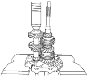
4. Assemble the main shaft completely, and then press the countershaft using a press to assemble the countershaft completely.
bmm6jm00000066
|
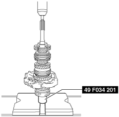
Counter 4th Gear Assembly Note
1. Assemble the counter 4th gear using the SST and a hammer.
bmm6jm00000067
|
4th Synchronizer Component, 3rd Synchronizer Component Assembly Note
1. Align the projections of each synchronizer cone with the positions of the gear and clutch hub grooves as shown in the figure and assemble.
bmm8um00000023
|
3rd/4th Clutch Hub, 3rd/4th Clutch Hub Sleeve Assembly Note
1. Assemble so that the surface with the 3rd/4th clutch hub groove is facing the transmission case side.
bmm8um00000024
|
2. Assemble so that the surface with the 3rd/4th clutch hub sleeve marking is facing the extension housing side.
3rd/4th Clutch Hub Component Assembly Note
1. Assemble the 3rd/4th clutch hub component using the SST and the press.
bmm6jm00000070
|
Locknut (Main Shaft) Assembly Note
1. Install the SST to the main shaft and secure it to the vise.
bmm6jm00000071
|
2. Operate the clutch hub sleeves to engage them with the 5th gear and 2nd gear, and lock the rotation of the main shaft.
3. Tighten a new locknut (main shaft) using the SST.
bmm6jm00000072
|
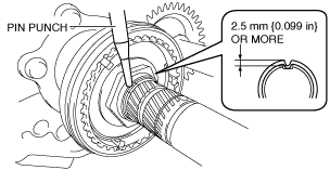
4. Crimp the locknut (main shaft).
bmm8um00000025
|
Washer Assembly Note
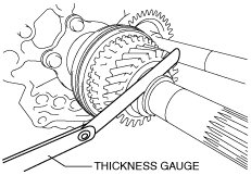
1. Assemble the washer which was removed during disassembly and a new snap ring.
2. Using a thickness gauge, measure the clearance between the snap ring and the washer.
bmm8um00000026
|
|
Washer thickness (mm {in}) |
|---|
|
6.2 {0.244}
|
|
6.3 {0.248}
|
|
6.4 {0.252}
|
|
6.5 {0.256}
|
|
6.6 {0.260}
|
|
6.7 {0.264}
|
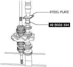
Countershaft Rear Bearing Assembly Note
1. Assemble the countershaft rear bearing using the SST and the press.
bmm8um00000027
|
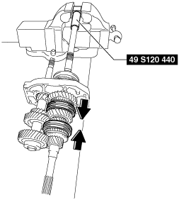
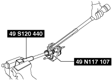
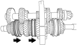
Locknut (Countershaft) Assembly Note
1. Install the SST (49 S120 440) to the main shaft and secure it to the vise.
bmm6jm00000076
|
2. Operate the clutch hub sleeves to engage them with the 5th gear and 1st gear, and lock the rotation of the countershaft.
3. Tighten a new locknut (countershaft).
4. Crimp the locknut (countershaft).
bmm8um00000028
|
Main Shaft Rear Bearing Assembly Note
1. Assemble the main shaft rear bearing using the SST.
bmm6jm00000078
|