|
amxzzn00001026
ENGINE CONTROL SYSTEM [SKYACTIV-G 1.5, SKYACTIV-G 2.0]
id0140g8139900
Outline
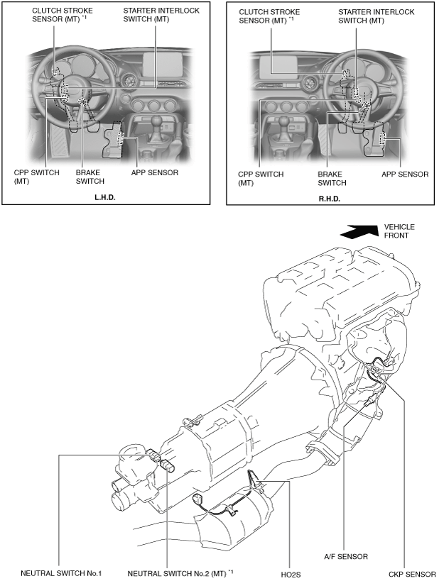
Structural View
Input device
amxzzn00001026
|
amxzzn00001043
|
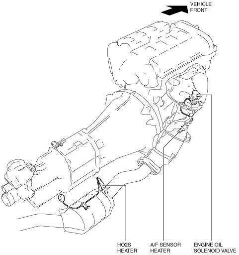
Output device
amxzzn00001044
|
amxzzn00001045
|
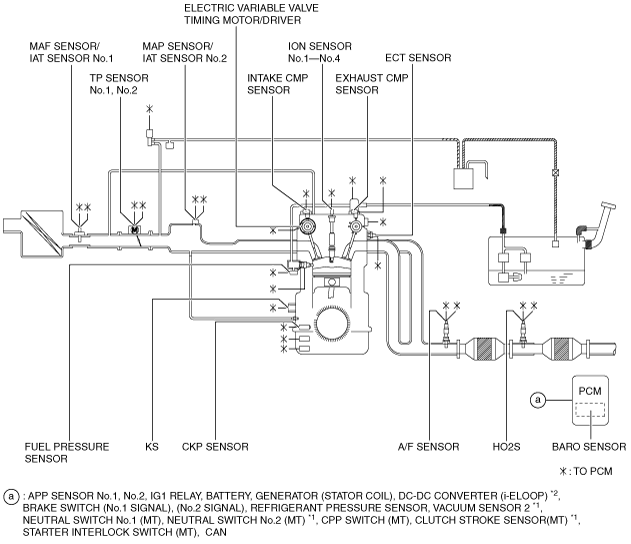
System Diagram
Input device
amxzzn00001046
|
Output device
amxzzn00001047
|
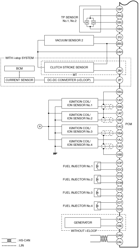
System Wiring Diagram
amxuuw00003759
|
amxzzw00003551
|
amxzzw00003552
|
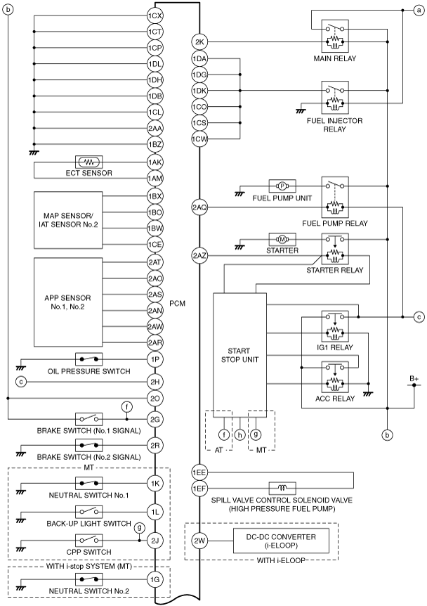
Block Diagram
amxzzn00001048
|
Relation Chart
Input device
|
Item |
 |
 |
 |
 |
 |
 |
 |
 |
 |
 |
 |
 |
 |
 |
 |
 |
 |
|---|---|---|---|---|---|---|---|---|---|---|---|---|---|---|---|---|---|
|
APP sensor No.1, No.2
|
×
|
×
|
×
|
|
×
|
×
|
×
|
×
|
×*2
|
×
|
|||||||
|
TP sensor No.1, No.2
|
×
|
×
|
|
×
|
×
|
||||||||||||
|
MAF sensor
|
×
|
×
|
×
|
×
|
|
×
|
×
|
×
|
×
|
×
|
×
|
×
|
×
|
||||
|
IAT sensor No.1
|
×
|
×
|
×
|
|
×
|
×
|
×
|
×
|
|||||||||
|
IAT sensor No.2
|
×
|
×
|
×
|
|
×
|
×
|
|||||||||||
|
MAP sensor
|
×
|
×
|
×
|
|
×
|
×
|
×
|
×
|
|||||||||
|
CKP sensor
|
×
|
×
|
×
|
×
|
×
|
×
|
×
|
×
|
×
|
×
|
×
|
×
|
×
|
×
|
×
|
×
|
|
|
Intake CMP sensor
|
×
|
×
|
×
|
|
×
|
×
|
|||||||||||
|
Exhaust CMP sensor
|
×
|
×
|
×
|
|
×
|
×
|
×
|
||||||||||
|
ECT sensor
|
×
|
×
|
×
|
×
|
|
×
|
×
|
×
|
×
|
×
|
×
|
×
|
×
|
×
|
×
|
||
|
Fuel pressure sensor
|
×
|
×
|
×
|
×
|
×
|
||||||||||||
|
BARO sensor
|
×
|
×
|
×
|
|
×
|
×
|
×
|
||||||||||
|
Vacuum sensor 2
|
×
|
||||||||||||||||
|
Ion sensor No.1—No.4
|
×
|
×
|
|
×
|
|||||||||||||
|
KS
|
|
×
|
|||||||||||||||
|
A/F sensor
|
×
|
|
×
|
||||||||||||||
|
HO2S
|
×
|
|
|||||||||||||||
|
Refrigerant pressure sensor
|
|
×
|
×
|
||||||||||||||
|
IG1 relay
|
×
|
×
|
×
|
×
|
×
|
×
|
×
|
×
|
×
|
×
|
|||||||
|
Brake switch (No.1 signal)
|
×
|
|
×
|
||||||||||||||
|
Brake switch (No.2 signal)
|
×
|
|
|||||||||||||||
|
CPP switch (MT)
|
×
|
×
|
|
×
|
×
|
×
|
|||||||||||
|
Starter interlock switch (MT)
|
|
×
|
|||||||||||||||
|
Clutch stroke sensor (MT) *1
|
×
|
||||||||||||||||
|
Neutral switch No.1 (MT)
|
×
|
×
|
|
×
|
×
|
×
|
|||||||||||
|
Neutral switch No.2 (MT) *1
|
×
|
||||||||||||||||
|
Electric variable valve timing motor/driver
|
×
|
|
×
|
||||||||||||||
|
Battery
|
×
|
×
|
×
|
×
|
×
|
×
|
×
|
||||||||||
|
Generator (Stator coil)
|
×
|
|
|||||||||||||||
|
DC-DC converter (i-ELOOP) *2
|
×
|
||||||||||||||||
|
CAN related parts*3
|
×
|
×
|
×
|
×
|
×
|
×
|
×
|
×
|
Output device
|
Item |
|
|
|
|
|
|
|
|
|
|
|
|
|
|
|
|
|
|---|---|---|---|---|---|---|---|---|---|---|---|---|---|---|---|---|---|
|
Main relay
|
×
|
|
|||||||||||||||
|
Throttle valve actuator
|
×
|
|
×
|
||||||||||||||
|
Electric variable valve timing motor/driver
|
×
|
×
|
|
×
|
|||||||||||||
|
Electric variable valve timing relay
|
×
|
|
×
|
||||||||||||||
|
OCV
|
×
|
|
|||||||||||||||
|
Fuel injector No.1—No.4
|
×
|
|
×
|
||||||||||||||
|
Fuel injector relay
|
×
|
|
×
|
||||||||||||||
|
Fuel pump relay
|
×
|
||||||||||||||||
|
Spill valve control solenoid valve (High pressure fuel pump)
|
|
×
|
|||||||||||||||
|
Ignition coil No.1—No.4
|
|
×
|
×
|
||||||||||||||
|
Purge solenoid valve
|
|
×
|
|||||||||||||||
|
A/F sensor heater
|
|
×
|
|||||||||||||||
|
HO2S heater
|
|
×
|
|||||||||||||||
|
A/C relay
|
|
×
|
|||||||||||||||
|
Cooling fan relay
|
|
×
|
|||||||||||||||
|
Fan control module
|
|
×
|
|||||||||||||||
|
Starter relay
|
|
×
|
×
|
||||||||||||||
|
Generator (Field coil)
|
|
×
|
×
|
||||||||||||||
|
Engine oil solenoid valve
|
|
×
|