 |
am3zzw00013565
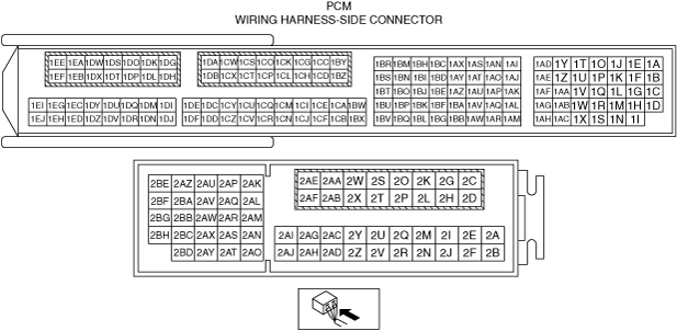
PCM INSPECTION [SKYACTIV-G 1.5, SKYACTIV-G 2.0]
id0140g8802500
Without Using the M-MDS
Terminal voltage table (Reference)
am3zzw00013565
|
|
Terminal |
Signal |
Connected to |
Test condition |
Voltage (V) |
inspection item |
|
|---|---|---|---|---|---|---|
|
1A*1
|
CAN2_H
|
CAN system related modules
|
Because this terminal is for CAN, integrity determination by terminal voltage is not possible.
|
• Related wiring harness
|
||
|
1B*1
|
CAN2_L
|
CAN system related modules
|
Because this terminal is for CAN, integrity determination by terminal voltage is not possible.
|
• Related wiring harness
|
||
|
1C
|
—
|
—
|
—
|
—
|
—
|
|
|
1D
|
Knocking (–)
|
KS
|
Ignition switched ON (engine off)
|
Approx. 0.02
|
• KS
• Related wiring harness
|
|
|
1E
|
—
|
—
|
—
|
—
|
—
|
|
|
1F
|
—
|
—
|
—
|
—
|
—
|
|
|
1G*5
|
Neutral switch No.2
|
Neutral switch No.2
|
Switch ignition ON (engine off)
|
Neutral
|
Below 1.0
|
• Neutral switch No.2
• Related wiring harness
|
|
Except above
|
B+
|
|||||
|
1H
|
Knocking (+)
|
KS
|
Ignition switched ON (engine off)
|
Approx. 2.44
|
• KS
• Related wiring harness
|
|
|
1I
|
GND
|
Sensor shield
|
Under any condition
|
Below 1.0
|
• Related wiring harness
|
|
|
1J
|
Electric variable valve timing motor (rotation direction)
|
Electric variable valve timing motor/driver
|
• Electric variable valve timing motor/driver
• Related wiring harness
|
|||
|
1K*2
|
Neutral position
|
Neutral switch No.1
|
Shift lever is at neutral position
|
Below 1.0
|
• Neutral switch No.1
• Related wiring harness
|
|
|
Shift lever is not at neutral position
|
B+
|
|||||
|
1L*2
|
Back-up light
|
Back-up light switch
|
Shift lever is at reverse position
|
Below 1.0
|
• Back-up light switch
• Related wiring harness
|
|
|
Shift lever is not at reverse position
|
B+
|
|||||
|
1M
|
—
|
—
|
—
|
—
|
—
|
|
|
1N
|
—
|
—
|
—
|
—
|
—
|
|
|
1O
|
Electric variable valve timing motor (rotation pulse)
|
Electric variable valve timing motor/driver
|
• Electric variable valve timing motor/driver
• Related wiring harness
|
|||
|
1P
|
Oil pressure
|
Oil pressure switch
|
Ignition switched ON (engine off)
|
Below 1.0
|
• Oil pressure switch
• Related wiring harness
|
|
|
Idle (after warm up and no load)
|
B+
|
|||||
|
1Q
|
—
|
—
|
—
|
—
|
—
|
|
|
1R
|
—
|
—
|
—
|
—
|
—
|
|
|
1S
|
—
|
—
|
—
|
—
|
—
|
|
|
1T
|
Exhaust CMP
|
Exhaust CMP sensor
|
(See Exhaust CMP signal.)
|
• Exhaust CMP sensor
• Related wiring harness
|
||
|
1U
|
—
|
—
|
—
|
—
|
—
|
|
|
1V
|
—
|
—
|
—
|
—
|
—
|
|
|
1W
|
A/F
|
A/F sensor
|
Idle (after warm up and no load)
|
Approx. 4.16
|
• A/F sensor
• Related wiring harness
|
|
|
1X
|
GND
|
Exhaust CMP sensor
|
Under any condition
|
Below 1.0
|
• Related wiring harness
|
|
|
1Y
|
Intake CMP
|
Intake CMP sensor
|
(See Intake CMP signal.)
|
• Intake CMP sensor
• Related wiring harness
|
||
|
1Z*3
|
Generator output voltage
|
Generator
|
• Generator
• Related wiring harness
|
|||
|
1AA
|
—
|
—
|
—
|
—
|
—
|
|
|
1AB
|
A/F
|
A/F sensor
|
Idle (after warm up and no load): 0 mA
|
• A/F sensor
• Related wiring harness
|
||
|
1AC
|
GND
|
Intake CMP sensor
|
Under any condition
|
Below 1.0
|
• Related wiring harness
|
|
|
1AD
|
CKP
|
CKP sensor
|
(See CKP signal.)
|
• CKP sensor
• Related wiring harness
|
||
|
1AE
|
Electric variable valve timing driver (diagnostic)
|
Electric variable valve timing motor/driver
|
• Electric variable valve timing motor/driver
• Related wiring harness
|
|||
|
1AF*4
|
Generator output voltage
|
Generator
|
• Generator
• Related wiring harness
|
|||
|
1AG
|
A/F
|
A/F sensor
|
Idle (after warm up and no load)
|
Approx. 3.98
|
• A/F sensor
• Related wiring harness
|
|
|
1AH
|
GND
|
CKP sensor
|
Under any condition
|
Below 1.0
|
• Related wiring harness
|
|
|
1AI
|
Purge control
|
Purge solenoid valve
|
(See Purge control.)
|
• Purge solenoid valve
• Related wiring harness
|
||
|
1AJ
|
IGT4
|
Ignition coil No.4
|
• Ignition coil No.4
• Related wiring harness
|
|||
|
1AK
|
ECT
|
ECT sensor
|
Ignition switched ON (engine off)
|
ECT 20 °C
{68 °F}
|
Approx. 3.10
|
• ECT sensor
• Related wiring harness
|
|
ECT 40 °C
{104 °F}
|
Approx. 2.17
|
|||||
|
ECT 60 °C
{140 °F}
|
Approx. 1.40
|
|||||
|
ECT 80 °C
{176 °F}
|
Approx. 0.87
|
|||||
|
ECT 100 °C
{212 °F}
|
Approx. 0.54
|
|||||
|
1AL
|
—
|
—
|
—
|
—
|
—
|
|
|
1AM
|
GND
|
ECT sensor
|
Under any condition
|
Below 1.0
|
• Related wiring harness
|
|
|
1AN
|
Hydraulic variable valve timing control
|
OCV
|
• OCV
• Related wiring harness
|
|||
|
1AO
|
IGT3
|
Ignition coil No.3
|
• Ignition coil No.3
• Related wiring harness
|
|||
|
1AP
|
—
|
—
|
—
|
—
|
—
|
|
|
1AQ
|
—
|
—
|
—
|
—
|
—
|
|
|
1AR
|
—
|
—
|
—
|
—
|
—
|
|
|
1AS
|
Engine oil control
|
Engine oil solenoid valve
|
(See Engine oil control signal.)
|
• Engine oil solenoid valve
• Related wiring harness
|
||
|
1AT
|
IGT2
|
Ignition coil No.2
|
• Ignition coil No.2
• Related wiring harness
|
|||
|
1AU
|
—
|
—
|
—
|
—
|
—
|
|
|
1AV
|
Ion (No.4)
|
Ion sensor No.4
|
Idle (after warm up and no load)
|
Approx. 4.42
|
• Ion sensor No.4
• Related wiring harness
|
|
|
1AW
|
—
|
—
|
—
|
—
|
—
|
|
|
1AX
|
—
|
—
|
—
|
—
|
—
|
|
|
1AY
|
IGT1
|
Ignition coil No.1
|
• Ignition coil No.1
• Related wiring harness
|
|||
|
1AZ
|
Electric variable valve timing control
|
Electric variable valve timing motor/driver
|
• Electric variable valve timing motor/driver
• Related wiring harness
|
|||
|
1BA
|
Ion (No.3)
|
Ion sensor No.3
|
Idle (after warm up and no load)
|
Approx. 4.42
|
• Ion sensor No.3
• Related wiring harness
|
|
|
1BB
|
GND
|
Sensor shield
|
Under any condition
|
Below 1.0
|
• Related wiring harness
|
|
|
1BC
|
—
|
—
|
—
|
—
|
—
|
|
|
1BD
|
—
|
—
|
—
|
—
|
—
|
|
|
1BE*4
|
Generator field coil control
|
Generator
|
• Generator
• Related wiring harness
|
|||
|
1BF
|
Ion (No.2)
|
Ion sensor No.2
|
Idle (after warm up and no load)
|
Approx. 4.43
|
• Ion sensor No.2
• Related wiring harness
|
|
|
1BG
|
GND
|
Sensor shield
|
Under any condition
|
Below 1.0
|
• Related wiring harness
|
|
|
1BH
|
—
|
—
|
—
|
—
|
—
|
|
|
1BI
|
—
|
—
|
—
|
—
|
—
|
|
|
1BJ
|
Constant voltage (Vref)
|
Fuel pressure sensor
|
Ignition switched ON (engine off)
|
Approx. 5.02
|
• Related wiring harness
|
|
|
1BK
|
Ion (No.1)
|
Ion sensor No.1
|
Idle (after warm up and no load)
|
Approx. 4.45
|
• Ion sensor No.1
• Related wiring harness
|
|
|
1BL
|
GND
|
Sensor shield
|
Under any condition
|
Below 1.0
|
• Related wiring harness
|
|
|
1BM
|
—
|
—
|
—
|
—
|
—
|
|
|
1BN
|
Constant voltage (Vref)
|
CKP sensor
|
Ignition switched ON (engine off)
|
Approx. 5.02
|
• Related wiring harness
|
|
|
1BO
|
Constant voltage (Vref)
|
MAP sensor
|
Ignition switched ON (engine off)
|
Approx. 5.03
|
• Related wiring harness
|
|
|
1BP
|
TP (No.1)
|
TP sensor No.1
|
Ignition switched ON (engine off)
|
Accelerator pedal released
|
Approx. 1.13
|
• TP sensor No.1
• Related wiring harness
|
|
Accelerator pedal fully depressed
|
Approx. 4.62
|
|||||
|
1BQ
|
GND
|
TP sensor No.1, TP sensor No.2
|
Under any condition
|
Below 1.0
|
• Related wiring harness
|
|
|
1BR*3
|
Generator field coil control
|
Generator
|
• Generator
• Related wiring harness
|
|||
|
1BS
|
Constant voltage (Vref)
|
TP sensor No.1, TP sensor No.2
|
Ignition switched ON (engine off)
|
Approx. 5.02
|
• Related wiring harness
|
|
|
1BT
|
—
|
—
|
—
|
—
|
—
|
|
|
1BU
|
TP (No.2)
|
TP sensor No.2
|
Ignition switched ON (engine off)
|
Accelerator pedal released
|
Approx. 3.92
|
• TP sensor No.2
• Related wiring harness
|
|
Accelerator pedal fully depressed
|
Approx. 0.41
|
|||||
|
1BV
|
—
|
—
|
—
|
—
|
—
|
|
|
1BW
|
MAP
|
MAP sensor
|
Ignition switched ON (engine off)
|
Approx. 4.12
|
• MAP sensor
• Related wiring harness
|
|
|
Idle (after warm up and no load)
|
Approx. 2.13
|
|||||
|
Racing
(Engine speed: 2,000 rpm)
|
Approx. 0.86
|
|||||
|
1BX
|
GND
|
MAP sensor, IAT sensor No.2
|
Under any condition
|
Below 1.0
|
• Related wiring harness
|
|
|
1BY
|
A/F sensor heater control
|
A/F sensor heater
|
• A/F sensor heater
• Related wiring harness
|
|||
|
1BZ
|
GND
|
GND
|
Under any condition
|
Below 1.0
|
• Related wiring harness
|
|
|
1CA
|
Fuel pressure
|
Fuel pressure sensor
|
Ignition switched ON (engine off)
|
Approx. 1.22
|
• Fuel pressure sensor
• Related wiring harness
|
|
|
Idle (after warm up and no load)
|
Approx. 1.21
|
|||||
|
1CB
|
GND
|
Fuel pressure sensor
|
Under any condition
|
Below 1.0
|
• Related wiring harness
|
|
|
1CC
|
Drive-by-wire control (–)
|
Throttle valve actuator
|
Idle (after warm up)
Because the drive-by-wire control (-) terminal value varies depending on the vehicle, examination using only the ICC terminal is not possible. When performing the inspection, perform it together with the ICG terminal.
• Type A
• Type B
|
• Throttle valve actuator
• Related wiring harness
|
||
|
1CD
|
—
|
—
|
—
|
—
|
—
|
|
|
1CE
|
IAT (No.2)
|
IAT sensor No.2
|
Ignition switched ON (engine off)
|
IAT 20 °C
{68 °F}
|
Approx. 3.57
|
• IAT sensor No.2
• Related wiring harness
|
|
IAT 40 °C
{104 °F}
|
Approx. 2.70
|
|||||
|
IAT 60 °C
{140 °F}
|
Approx. 1.87
|
|||||
|
1CF
|
—
|
—
|
—
|
—
|
—
|
|
|
1CG
|
Drive-by-wire control (+)
|
Throttle valve actuator
|
• Throttle valve actuator
• Related wiring harness
|
|||
|
1CH
|
—
|
—
|
—
|
—
|
—
|
|
|
1CI
|
—
|
—
|
—
|
—
|
—
|
|
|
1CJ
|
—
|
—
|
—
|
—
|
—
|
|
|
1CK
|
Battery voltage
|
Main relay
|
Ignition switched ON (engine off)
|
B+
|
• Main relay
• Related wiring harness
|
|
|
1CL
|
GND
|
GND
|
Under any condition
|
Below 1.0
|
• Related wiring harness
|
|
|
1CM
|
—
|
—
|
—
|
—
|
—
|
|
|
1CN
|
—
|
—
|
—
|
—
|
—
|
|
|
1CO
|
Battery voltage
|
Fuel injector relay
|
Ignition switched ON (engine off)
|
B+
|
• Fuel injector relay
• Related wiring harness
|
|
|
1CP
|
GND
|
GND
|
Under any condition
|
Below 1.0
|
• Related wiring harness
|
|
|
1CQ
|
—
|
—
|
—
|
—
|
—
|
|
|
1CR
|
—
|
—
|
—
|
—
|
—
|
|
|
1CS
|
Battery voltage
|
Fuel injector relay
|
Ignition switched ON (engine off)
|
B+
|
• Fuel injector relay
• Related wiring harness
|
|
|
1CT
|
GND
|
GND
|
Under any condition
|
Below 1.0
|
• Related wiring harness
|
|
|
1CU
|
—
|
—
|
—
|
—
|
—
|
|
|
1CV
|
—
|
—
|
—
|
—
|
—
|
|
|
1CW
|
Battery voltage
|
Fuel injector relay
|
Ignition switched ON (engine off)
|
B+
|
• Fuel injector relay
• Related wiring harness
|
|
|
1CX
|
GND
|
GND
|
Under any condition
|
Below 1.0
|
• Related wiring harness
|
|
|
1CY
|
—
|
—
|
—
|
—
|
—
|
|
|
1CZ
|
—
|
—
|
—
|
—
|
—
|
|
|
1DA
|
Battery voltage
|
Fuel injector relay
|
Ignition switched ON (engine off)
|
B+
|
• Fuel injector relay
• Related wiring harness
|
|
|
1DB
|
GND
|
GND
|
Under any condition
|
Below 1.0
|
• Related wiring harness
|
|
|
1DC
|
—
|
—
|
—
|
—
|
—
|
|
|
1DD
|
—
|
—
|
—
|
—
|
—
|
|
|
1DE
|
—
|
—
|
—
|
—
|
—
|
|
|
1DF
|
—
|
—
|
—
|
—
|
—
|
|
|
1DG
|
Battery voltage
|
Fuel injector relay
|
Ignition switched ON (engine off)
|
B+
|
• Fuel injector relay
• Related wiring harness
|
|
|
1DH
|
GND
|
GND
|
Under any condition
|
Below 1.0
|
• Related wiring harness
|
|
|
1DI
|
—
|
—
|
—
|
—
|
—
|
|
|
1DJ
|
—
|
—
|
—
|
—
|
—
|
|
|
1DK
|
Battery voltage
|
Fuel injector relay
|
Ignition switched ON (engine off)
|
B+
|
• Fuel injector relay
• Related wiring harness
|
|
|
1DL
|
GND
|
GND
|
Under any condition
|
Below 1.0
|
• Related wiring harness
|
|
|
1DM
|
—
|
—
|
—
|
—
|
—
|
|
|
1DN
|
—
|
—
|
—
|
—
|
—
|
|
|
1DO
|
Fuel injection control (–)
|
Fuel injector No.1
|
• Fuel injector No.1
• Related wiring harness
|
|||
|
1DP
|
Fuel injection control (+)
|
Fuel injector No.1
|
• Fuel injector No.1
• Related wiring harness
|
|||
|
1DQ
|
—
|
—
|
—
|
—
|
—
|
|
|
1DR
|
—
|
—
|
—
|
—
|
—
|
|
|
1DS
|
Fuel injection control (–)
|
Fuel injector No.4
|
• Fuel injector No.4
• Related wiring harness
|
|||
|
1DT
|
Fuel injection control (+)
|
Fuel injector No.4
|
• Fuel injector No.4
• Related wiring harness
|
|||
|
1DU
|
—
|
—
|
—
|
—
|
—
|
|
|
1DV
|
—
|
—
|
—
|
—
|
—
|
|
|
1DW
|
Fuel injection control (–)
|
Fuel injector No.2
|
• Fuel injector No.2
• Related wiring harness
|
|||
|
1DX
|
Fuel injection control (+)
|
Fuel injector No.2
|
• Fuel injector No.2
• Related wiring harness
|
|||
|
1DY
|
—
|
—
|
—
|
—
|
—
|
|
|
1DZ
|
—
|
—
|
—
|
—
|
—
|
|
|
1EA
|
Fuel injection control (–)
|
Fuel injector No.3
|
• Fuel injector No.3
• Related wiring harness
|
|||
|
1EB
|
Fuel injection control (+)
|
Fuel injector No.3
|
• Fuel injector No.3
• Related wiring harness
|
|||
|
1EC
|
—
|
—
|
—
|
—
|
—
|
|
|
1ED
|
—
|
—
|
—
|
—
|
—
|
|
|
1EE
|
High pressure fuel pump control (+)
|
High pressure fuel pump
|
• High pressure fuel pump
• Related wiring harness
|
|||
|
1EF
|
High pressure fuel pump control (–)
|
High pressure fuel pump
|
• High pressure fuel pump
• Related wiring harness
|
|||
|
1EG
|
—
|
—
|
—
|
—
|
—
|
|
|
1EH
|
—
|
—
|
—
|
—
|
—
|
|
|
1EI
|
—
|
—
|
—
|
—
|
—
|
|
|
1EJ
|
—
|
—
|
—
|
—
|
—
|
|
|
2A
|
—
|
—
|
—
|
—
|
—
|
|
|
2B
|
—
|
—
|
—
|
—
|
—
|
|
|
2C
|
HO2S heater control
|
HO2S heater
|
(See HO2S heater control signal.)
|
• HO2S heater
• Related wiring harness
|
||
|
2D
|
—
|
—
|
—
|
—
|
—
|
|
|
2E
|
—
|
—
|
—
|
—
|
—
|
|
|
2F
|
—
|
—
|
—
|
—
|
—
|
|
|
2G
|
Brake (No.1)
|
Brake switch (No.1 signal)
|
Brake pedal released
|
Below 1.0
|
• Brake switch (No.1 signal)
• Related wiring harness
|
|
|
Brake pedal fully depressed
|
B+
|
|||||
|
2H
|
Ignition (IG1)
|
IG1 relay
|
Ignition switched ON (engine off)
|
B+
|
• IG1 relay
• Related wiring harness
|
|
|
2I
|
Ambient temperature
|
Ambient temperature sensor
|
Ignition switched ON (engine off)
|
AAT 20 °C
{68 °F}
|
Approx. 2.70
|
• Ambient temperature sensor
• Related wiring harness
|
|
AAT 30 °C
{104 °F}
|
Approx. 1.80
|
|||||
|
2J*2
|
CPP
|
CPP switch, start stop unit
|
Clutch pedal fully depressed
|
Below 1.0
|
• CPP switch
• Start stop unit
• Related wiring harness
|
|
|
Clutch pedal released
|
B+
|
|||||
|
2K
|
Main relay control
|
Main relay
|
Ignition switched ON (engine off)
|
Approx. 0.87
|
• Main relay
• Related wiring harness
|
|
|
2L
|
—
|
—
|
—
|
—
|
—
|
|
|
2M*5
|
Clutch stroke sensor
|
Clutch stroke sensor
|
Ignition switched ON (engine off)
|
Clutch pedal released
|
Approx. 0.6
|
• Clutch stroke sensor
• Related wiring harness
|
|
Clutch pedal fully depressed
|
Approx. 4.5
|
|||||
|
2N
|
—
|
—
|
—
|
—
|
—
|
|
|
2O
|
Battery voltage
|
Battery
|
Under any condition
|
B+
|
• Battery
• Related wiring harness
|
|
|
2P*3
|
DC-DC converter control
|
DC-DC converter (i-ELOOP)
|
Ignition switched ON (engine off)
|
Approx. 0
|
• DC-DC converter (i-ELOOP)
• Related wiring harness
|
|
|
2Q
|
Power brake unit vacuum
|
Vacuum sensor 2
|
Idle (after warm up and no load)
|
Brake pedal released
|
Approx. 0.98
|
• Vacuum sensor 2
• Related wiring harness
|
|
2R
|
Brake (No.2)
|
Brake switch (No.2 signal)
|
Brake pedal released
|
Below 1.0
|
• Brake switch (No.2 signal)
• Related wiring harness
|
|
|
Brake pedal fully depressed
|
B+
|
|||||
|
2S
|
Battery voltage
|
Main relay
|
Ignition switched ON (engine off)
|
B+
|
• Main relay
• Related wiring harness
|
|
|
2T
|
Battery voltage
|
Main relay
|
Ignition switched ON (engine off)
|
B+
|
• Main relay
• Related wiring harness
|
|
|
2U
|
IAT (No.1)
|
IAT sensor No.1
|
Ignition switched ON (engine off)
|
IAT 20 °C
{68 °F}
|
Approx. 2.70
|
• IAT sensor No.1
• Related wiring harness
|
|
IAT 40 °C
{104 °F}
|
Approx. 1.80
|
|||||
|
IAT 60 °C
{140 °F}
|
Approx. 1.20
|
|||||
|
2V
|
—
|
—
|
—
|
—
|
—
|
|
|
2W*3
|
DC-DC converter (i-ELOOP) control
|
DC-DC converter (i-ELOOP)
|
Idle (after warm up and no load)
|
Approx. 10.76
|
• DC-DC converter (i-ELOOP)
• Related wiring harness
|
|
|
2X
|
Fan control
|
Fan control module
|
(See Cooling fan control signal.)
|
• Fan control module
• Related wiring harness
|
||
|
2Y
|
—
|
—
|
—
|
—
|
—
|
|
|
2Z
|
—
|
—
|
—
|
—
|
—
|
|
|
2AA
|
GND
|
GND
|
Under any condition
|
Below 1.0
|
• Related wiring harness
|
|
|
2AB
|
—
|
—
|
—
|
—
|
—
|
|
|
2AC
|
—
|
—
|
—
|
—
|
—
|
|
|
2AD
|
GND
|
Sensor shield
|
Under any condition
|
Below 1.0
|
• Related wiring harness
|
|
|
2AE
|
—
|
—
|
—
|
—
|
—
|
|
|
2AF
|
A/C cut-off control
|
A/C relay
|
A/C relay OFF
|
B+
|
• A/C relay
• Related wiring harness
|
|
|
A/C relay ON
|
Below 1.0
|
|||||
|
2AG
|
HO2S (–)
|
HO2S
|
Idle (after warm up and no load)
|
Approx. 1.61
|
• HO2S
• Related wiring harness
|
|
|
2AH
|
GND
|
Vacuum sensor 2, clutch stroke sensor*5
|
Under any condition
|
Below 1.0
|
• Related wiring harness
|
|
|
2AI
|
HO2S (+)
|
HO2S
|
Idle (after warm up and no load)
|
Approx. 1.68
|
• HO2S
• Related wiring harness
|
|
|
2AJ
|
GND
|
Ambient temperature sensor, refrigerant pressure sensor
|
Under any condition
|
Below 1.0
|
• Related wiring harness
|
|
|
2AK
|
HS CAN_H
|
CAN system related modules
|
Because this terminal is for CAN, integrity determination by terminal voltage is not possible.
|
• Related wiring harness
|
||
|
2AL
|
HS CAN_L
|
CAN system related modules
|
Because this terminal is for CAN, integrity determination by terminal voltage is not possible.
|
• Related wiring harness
|
||
|
2AM
|
—
|
—
|
—
|
—
|
—
|
|
|
2AN
|
APP (No.1)
|
APP sensor No.1
|
Ignition switched ON (engine off)
|
Accelerator pedal released
|
Approx. 0.81
|
• APP sensor No.1
• Related wiring harness
|
|
Accelerator pedal fully depressed
|
Approx. 4.54
|
|||||
|
2AO
|
GND
|
APP sensor No.1
|
Under any condition
|
Below 1.0
|
• Related wiring harness
|
|
|
2AP
|
—
|
—
|
—
|
—
|
—
|
|
|
2AQ
|
Fuel pump control
|
Fuel pump relay
|
Ignition switched ON (engine off)
|
B+
|
• Fuel pump relay
• Related wiring harness
|
|
|
Idle (after warm up and no load)
|
Below 1.0
|
|||||
|
2AR
|
Constant voltage (Vref)
|
APP sensor No.1
|
Ignition switched ON (engine off)
|
Approx. 5.02
|
• Related wiring harness
|
|
|
2AS
|
APP (No.2)
|
APP sensor No.2
|
Ignition switched ON (engine off)
|
Accelerator pedal released
|
Approx. 0.42
|
• APP sensor No.2
• Related wiring harness
|
|
Accelerator pedal fully depressed
|
Approx. 2.28
|
|||||
|
2AT
|
GND
|
APP sensor No.2
|
Under any condition
|
Below 1.0
|
• Related wiring harness
|
|
|
2AU
|
Cooling fan control
|
Cooling fan relay
|
Cooling fan operating
|
Below 1.0
|
• Cooling fan relay
• Related wiring harness
|
|
|
Cooling fan not operating
|
B+
|
|||||
|
2AV
|
—
|
—
|
—
|
—
|
—
|
|
|
2AW
|
Constant voltage (Vref)
|
APP sensor No.2
|
Ignition switched ON (engine off)
|
Approx. 5.02
|
• Related wiring harness
|
|
|
2AX
|
Refrigerant pressure
|
Refrigerant pressure sensor
|
Refrigerant pressure: 1.0 MPa {10 kgf/cm2, 145 psi}
|
Approx. 1.58
|
• Refrigerant pressure sensor
• Related wiring harness
|
|
|
Refrigerant pressure: 1.1 MPa {11 kgf/cm2, 160 psi}
|
Approx. 1.75
|
|||||
|
Refrigerant pressure: 1.2 MPa {12 kgf/cm2, 174 psi}
|
Approx. 1.88
|
|||||
|
2AY
|
GND
|
MAF sensor, IAT sensor No.1
|
Under any condition
|
Below 1.0
|
• Related wiring harness
|
|
|
2AZ
|
Starter cut-off control
|
Starter relay, start stop unit
|
Ignition switched ON (engine off)
|
MT
• Clutch pedal released
AT
• Selector lever position is not P or N position
|
B+
|
• Starter relay
• Start stop unit
• Related wiring harness
|
|
MT
• Clutch pedal fully depressed
AT
• Selector lever position is P or N position
|
Below 1.0
|
|||||
|
2BA
|
—
|
—
|
—
|
—
|
—
|
|
|
2BB
|
Constant voltage (Vref)
|
Refrigerant pressure sensor, MAF sensor
|
Ignition switched ON (engine off)
|
Approx. 5.03
|
• Related wiring harness
|
|
|
2BC
|
MAF
|
MAF sensor
|
Ignition switched ON (engine off)
|
Approx. 0.75
|
• MAF sensor
• Related wiring harness
|
|
|
Idle (after warm up and no load)
|
Approx. 1.13
|
|||||
|
Racing
(Engine speed: 2,000 rpm)
|
Approx. 1.31
|
|||||
|
2BD
|
Selector lever position*1
|
TR switch, start stop unit
|
Selector lever position is not P or N position
|
B+
|
• TR switch
• Start stop unit
• Related wiring harness
|
|
|
Selector lever position is P or N position
|
Below 1.0
|
|||||
|
Starter interlock*2
|
Starter interlock switch, start stop unit
|
Clutch pedal fully depressed
|
Below 1.0
|
• Starter interlock switch
• Start stop unit
• Related wiring harness
|
||
|
Clutch pedal released
|
B+
|
|||||
|
2BE
|
—
|
—
|
—
|
—
|
—
|
|
|
2BF
|
—
|
—
|
—
|
—
|
—
|
|
|
2BG
|
Constant voltage (Vref)
|
Vacuum sensor 2, clutch stroke sensor*5
|
Switch ignition ON (engine off)
|
Approx. 5.02
|
• Related wiring harness
|
|
|
2BH
|
—
|
—
|
—
|
—
|
—
|
|
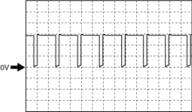
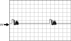
Inspection Using An Oscilloscope (Reference)
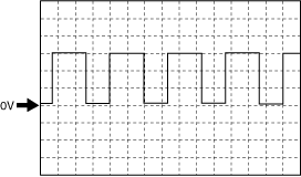
Electric variable valve timing motor (rotation direction) signal
adejjw00007909
|
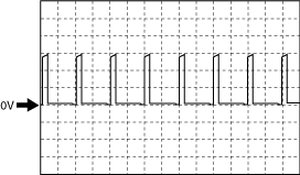
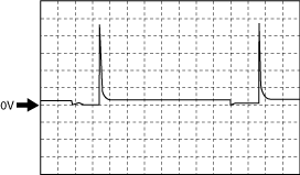
Electric variable valve timing motor (rotation pulse) signal
adejjw00007910
|
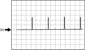
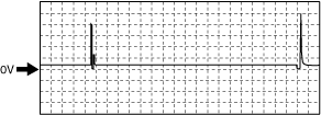
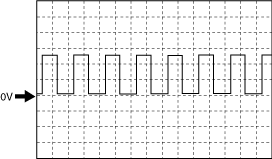
Exhaust CMP signal
adejjw00007911
|
Intake CMP signal
adejjw00007911
|
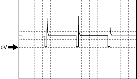
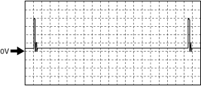
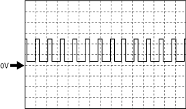
CKP signal
adejjw00007912
|
Electric variable valve timing driver (diagnostic) signal
adejjw00007913
|
Generator output voltage (without i-ELOOP)
adejjw00007914
|
Generator output voltage (with i-ELOOP)
amxzzw00003561
|
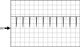
Purge control
adejjw00007915
|
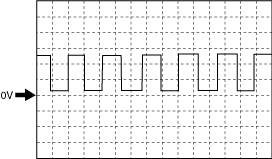
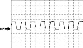
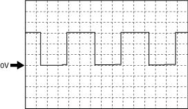
IGT1, IGT2, IGT3, IGT4 control
amxuuw00003768
|
Hydraulic variable valve timing control signal
adejjw00007917
|
Engine oil control signal
adejjw00007918
|
Electric variable valve timing control signal
adejjw00007919
|
Generator field coil control signal (without i-ELOOP)
adejjw00007920
|
Generator field coil control signal (with i-ELOOP)
amxzzw00003562
|
A/F sensor heater control signal
am3zzw00015902
|
Drive-by-wire control (+) signal
Type A
am3zzw00012795
|
Type B
ac3jjw00004192
|
Fuel injection control (-) signal
adejjw00007923
|
Fuel injection control (+) signal
adejjw00007924
|
High pressure fuel pump control (+) signal
am3zzw00012796
|
High pressure fuel pump control (-) signal
am3zzw00015903
|
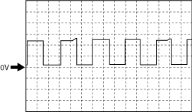
HO2S heater control signal
adejjw00007927
|
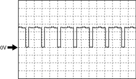
Cooling fan control signal
amxuuw00003770
|
Using The M-MDS
1. Connect the M-MDS to the DLC‐2.
2. Switch the ignition ON (engine off).
3. Measure the PID value.
|
Item |
Unit/Condition |
Definition |
Value type |
Condition/Specification (Reference) |
PCM terminal |
|---|---|---|---|---|---|
|
AC_PRES
|
KPa {MPa}, mBar {Bar}, psi, in H20
|
Refrigerant pressure input from refrigerant pressure sensor
|
Calculation
|
• Displays refrigerant pressure
|
2AX
|
|
V
|
Refrigerant pressure sensor voltage
|
Input
|
• Refrigerant pressure is 547 kPa {5.58 kgf/cm2, 79.3 psi}: Approx. 0.91 V
• Refrigerant pressure is 757 kPa {7.72 kgf/cm2, 110 psi}: Approx. 1.22 V
• Refrigerant pressure is 1.17 MPa {11.9 kgf/cm2, 170 psi}: Approx. 1.84 V
|
||
|
AC_REQ
|
Off/On
|
A/C switch status received by PCM via CAN
|
Input
|
• A/C switch on: On
• A/C switch off: Off
|
CAN
(2AK, 2AL)
|
|
ACCS
|
Off/On
|
A/C relay status input from A/C relay
|
Input
|
• A/C relay on: On
• A/C relay off: Off
|
2AF
|
|
ALTF
|
%
|
Field coil current control signal output to generator
|
Calculation
|
• Ignition switched ON (engine off): 0% (ECT is 80 °C {176 °F})
• Idle: Approx. 40.41% (ECT is 80 °C {176 °F})
• Racing (Engine speed is 2,000 rpm): 20.24% (ECT is 82 °C {180 °F})
• Racing (Engine speed is 4,000 rpm): 16.16% (ECT is 87 °C {189 °F})
• Idle (A/C on): Approx. 38.98% (ECT is 89 °C {192 °F})
|
1BE
|
|
ALTF_ACT*7
|
%
|
Actually measured value of field coil current signal input from generator
|
Calculation
|
• Displays actual generator field current control duty value
|
—
|
|
ALTT V*5
|
V
|
Generator output voltage
|
Input
|
• Idle (no E/L): Approx. 14 V (This is internal calculation value and differs from terminal voltage)
|
1AF
|
|
AMB_TEMP
|
°C, °F
|
Actually measured ambient temperature input from ambient temperature sensor
|
Calculation
|
• Displays ambient air temperature
|
2I
|
|
APP
|
%
|
Accelerator pedal opening angle (relative value) with the fully released status as 0% and fully depressed status as 100%
|
Calculation
|
• Accelerator pedal released: Approx. 0%
• Accelerator pedal fully depressed: Approx. 100%
|
—
|
|
APP1
|
%
|
Accelerator pedal opening angle (absolute value) input from APP sensor No.1
|
Calculation
|
• Accelerator pedal released: Approx. 15.29%
• Accelerator pedal fully depressed: Approx. 90.98%
|
2AN
|
|
V
|
APP sensor No.1 voltage
|
Input
|
• Accelerator pedal released: Approx. 0.77 V
• Accelerator pedal fully depressed: Approx. 4.55 V
|
||
|
APP2
|
%
|
Accelerator pedal opening angle (absolute value) input from APP sensor No.2
|
Calculation
|
• Accelerator pedal released: Approx. 7.84%
• Accelerator pedal fully depressed: Approx. 45.49%
|
2AS
|
|
V
|
APP sensor No.2 voltage
|
Input
|
• Accelerator pedal released: Approx. 0.38 V
• Accelerator pedal fully depressed: Approx. 2.27 V
|
||
|
ARPMDES
|
RPM
|
Target engine speed
|
Calculation
|
• Displays target engine speed
|
—
|
|
BARO
|
KPa {MPa}, mBar {Bar}, psi, in H20
|
Actually measured barometric pressure input from BARO sensor built into PCM
|
Calculation
|
• Displays BARO
|
—
|
|
BATT_CUR*3
|
A
|
Battery charge/discharge current
|
Calculation
|
• Displays battery charge/discharge current value
Ignition switched ON (engine off)
Idle (after warm up)
Racing (Engine speed is 2,000 rpm)
|
CAN
(2AK, 2AL)
|
|
BATT_DAY*3
|
—
|
Number of days elapsed since current sensor initialization
|
Calculation
|
• Displays vehicle battery days in service
|
CAN
(2AK, 2AL)
|
|
BATT_RES*3
|
—
|
Battery internal resistance (estimated)
|
Calculation
|
• Displays battery inferred internal resistance
Ignition switched ON (engine off)
Idle (after warm up)
Racing (Engine speed is 2,000 rpm)
|
CAN
(2AK, 2AL)
|
|
BATT_SOC*3
|
%
|
Battery charge condition (estimated)
|
Calculation
|
• Displays battery estimated state of charge
|
CAN
(2AK, 2AL)
|
|
BATT_TEMP*3
|
°C, °F
|
Battery temperature
|
Calculation
|
• Displays battery fluid temperature
Ignition switched ON (engine off)
Idle (after warm up)
Racing (Engine speed is 2,000 rpm)
|
CAN
(2AK, 2AL)
|
|
BATT_V*3
|
V
|
Battery voltage
|
Calculation
|
• Displays battery voltage
Ignition switched ON (engine off)
Idle (after warm up)
Racing (Engine speed is 2,000 rpm)
|
CAN
(2AK, 2AL)
|
|
BBP*3
|
KPa {MPa}, mBar {Bar}, psi, in H20
|
Power brake unit vacuum input from vacuum sensor 2
|
Calculation
|
• Displays power brake unit vacuum
Ignition switched ON (engine off)
Idle (after warm up)
Racing (Engine speed is 2,000 rpm)
Racing (Engine speed is 4,000 rpm)
|
2Q
|
|
V
|
vacuum sensor 2 voltage
|
Input
|
Ignition switched ON (engine off)
• Power brake unit vacuum is 20.09 kPa {0.2049 kgf/cm2, 2.914 psi}: Approx. 0.81 V
Idle (after warm up)
• Power brake unit vacuum is 23.95 kPa {0.2442 kgf/cm2, 3.474 psi}: Approx. 0.96 V
• Power brake unit vacuum is 23.77 kPa {0.2424 kgf/cm2, 3.448 psi}: Approx. 0.95 V
Racing (Engine speed is 2,000 rpm)
• Power brake unit vacuum is 23.95 kPa {0.2442 kgf/cm2, 3.474 psi}: Approx. 0.96 V
Racing (Engine speed is 4,000 rpm)
• Power brake unit vacuum is 22.23 kPa {0.2267 kgf/cm2, 3.224 psi}: Approx. 0.89 V
|
||
|
BFP*3
|
KPa {MPa}, mBar {Bar}, psi, in H20
|
Actually measured brake fluid pressure input from brake fluid pressure sensor built into DSC HU/CM via CAN
|
Calculation
|
• Displays brake fluid pressure
Ignition switched ON (engine off)
Idle (after warm up)
Racing (Engine speed is 2,000 rpm)
Racing (Engine speed is 4,000 rpm)
|
CAN
(2AK, 2AL)
|
|
BOO
|
High/Low
|
Brake switch (No.1 signal) input status
|
Calculation
|
• Brake pedal released: Low
• Brake pedal fully depressed: High
|
2G
|
|
BPA
|
High/Low
|
Brake switch (No.2 signal) input status
|
Calculation
|
• Brake pedal released: Low
• Brake pedal fully depressed: High
|
2R
|
|
CATT11_DSD
|
°C, °F
|
Estimated catalytic converter temperature
|
Calculation
|
• Displays estimated catalytic converter temperature
Idle (after warm up)
Racing (Engine speed is 2,000 rpm)
Racing (Engine speed is 4,000 rpm)
|
—
|
|
CHRGLP
|
Off/On
|
Charging system warning light illumination status
|
Calculation
|
• Charging system warning light illuminated: On
• Charging system warning light not illuminated: Off
|
—
|
|
CL_NMHC_MN_CP*6
|
—
|
Catalyst or catalyst for NMHC monitor completion
|
Calculation
|
• Displays the catalyst or catalyst for the NMHC monitor completion
|
—
|
|
CLU_CUT_SW*4
|
Off/On
|
Starter interlock switch status
|
Calculation
|
• Clutch pedal released: Off (starter interlock switch OFF)
• Clutch pedal fully depressed: On (starter interlock switch ON)
|
2BD
|
|
CMP_MNT_ENA*6
|
—
|
Emission-related part monitor operation condition
|
Calculation
|
• Displays the emission-related part monitor completion.
|
—
|
|
COMP3_MNT*6
|
—
|
Emission-related part monitor completion
|
Calculation
|
• Displays the emission-related part monitor operation condition.
|
—
|
|
CP_IGN_SP*6
|
—
|
Compression pressure monitor support condition
|
Calculation
|
• Displays the compression pressure monitor support condition.
|
—
|
|
CPP*1
|
Off/On
|
Clutch pedal position
|
Calculation
|
• Clutch pedal released: Off
• Clutch pedal fully depressed: On
|
2J
|
|
CPP*4
|
%
|
Clutch pedal position input from clutch stroke sensor
|
Calculation
|
• Clutch pedal released: approx. 0.2%
• Clutch pedal fully depressed: approx. 93.5%
|
2M
|
|
CPP/PNP*1
|
Off/On
|
Shift lever position
|
Calculation
|
• Neutral: On
• Other than neutral: Off
|
1K
|
|
CTLY_NMHC_MN*6
|
—
|
Catalyst or catalyst for NMHC monitor operation condition
|
Calculation
|
• Displays the catalyst or catalyst for the NMHC monitor operation condition.
|
—
|
|
ECT
|
°C, °F
|
Engine coolant temperature input from ECT sensor
|
Calculation
|
• Displays ECT
|
1AK
|
|
V
|
ECT sensor voltage
|
Input
|
Ignition switched ON (engine off)
• ECT is 92 °C {198 °F}: Approx. 0.65 V
Idle (after warm up)
• ECT is 93 °C {199 °F}: Approx. 0.64 V
Racing (Engine speed is 2,000 rpm)
• ECT is 92 °C {198 °F}: Approx. 0.66 V
Racing (Engine speed is 4,000 rpm)
• ECT is 93 °C {199 °F}: Approx. 0.64 V
|
||
|
EGR_VVT_MN_CP*6
|
—
|
EGR system or variable valve timing system monitor completion
|
Calculation
|
• Displays the EGR system or variable valve timing system monitor completion.
|
—
|
|
EGR_VVT_MNT*6
|
—
|
EGR system or variable valve timing system monitor operation condition
|
Calculation
|
• Displays the EGR system or variable valve timing system monitor operation condition.
|
—
|
|
EQ_RAT11
|
—
|
Excess air factor (estimated value) to theoretical air/fuel ratio (14.7) by fuel feedback control
|
Calculation
|
Ignition switched ON (engine off)
• ECT is 92 °C {198 °F}: Approx. 0.99
Idle (after warm up)
• ECT is 93 °C {199 °F}: Approx. 0.99
Racing (Engine speed is 2,000 rpm)
• ECT is 92 °C {198 °F}: Approx. 1
Racing (Engine speed is 4,000 rpm)
• ECT is 93 °C {199 °F}: Approx. 0.99
|
—
|
|
EQ_RAT11_DSD
|
—
|
Target excess air factor (estimated value) to theoretical air/fuel ratio (14.7) by fuel feedback control
|
Calculation
|
• Indicate target lambda (Excess air factor = supplied air amount / theoretical air/fuel ratio)
|
—
|
|
ETC_ACT
|
°(deg)
|
Actual throttle valve opening angle
|
Calculation
|
Ignition switched ON (engine off)
• Accelerator pedal released: Approx. 12.94 °
• Accelerator pedal fully depressed: Approx. 86.18 °
Idle (after warm up)
• Accelerator pedal released: Approx. 2.22 °
|
—
|
|
ETC_DSD
|
°(deg)
|
Target throttle valve opening angle
|
Calculation
|
• Displays target TP opening angle
Ignition switched ON (engine off)
|
—
|
|
%
|
Target throttle valve opening angle (percent)
|
Calculation
|
• Displays target TP opening angle (percent)
Ignition switched ON (engine off)
|
||
|
EVAP_SYS_MN*6
|
—
|
Evaporative emission control system monitor operation condition
|
Calculation
|
• Displays the evaporative emission control system monitor operation condition.
|
—
|
|
EVAP_SYS_MN_CP*6
|
—
|
Evaporative emission control system monitor completion
|
Calculation
|
• Displays the evaporative emission control system monitor completion.
|
—
|
|
EVAPCP
|
%
|
Purge solenoid valve control duty value
|
Calculation
|
• Idle (after warm up): 0% (Engine coolant temperature 59 °C {140 °F} or less)
• Racing (Engine speed 2,000 rpm): 0% (ECT is 94 °C {201 °F})
• Racing (Engine speed 4,000 rpm): Approx. 10.1% (ECT is 94 °C {201 °F})
|
1AI
|
|
FAN_DUTY
|
%
|
Fan control module control duty value
|
Calculation
|
Idle
• ECT is below 94 °C {201 °F}: Approx. 0%
• ECT is 94 °C {201 °F}: Approx. 33.43% (after a certain period has elapsed from when ECT reaches 94 °C {201 °F})
Racing (Engine speed is 4,000 rpm)
• ECT is 94 °C {201 °F}: Approx. 29.99% (after a certain period has elapsed from when ECT reaches 94 °C {201 °F})
|
2X
|
|
FAN1
|
Off/On
|
Cooling fan relay operation status
|
Calculation
|
• Cooling fan relay off: Off
• Cooling fan relay on: On
|
2AU
|
|
FIA
|
—
|
Fuel injection amount
|
Calculation
|
• Displays fuel injection amount
Idle (after warm up)
Racing (Engine speed is 2,000 rpm)
Racing (Engine speed is 4,000 rpm)
|
—
|
|
FLI
|
%
|
Fuel level
|
Calculation
|
• Fuel gauge level F: Approx. 100%
• Fuel gauge level E: Approx. 0%
|
CAN
(2AK, 2AL)
|
|
FP
|
Off/On
|
Fuel pump relay operation status
|
Calculation
|
• Ignition switched ON (engine off): Off
• Cranking: On
• Idle (after warm up): On
|
2AQ
|
|
FRP_A*6
|
KPa {MPa}, mBar {Bar}, psi, in H20
|
Actual fuel distributor pressure
|
Calculation
|
• Displays the actual fuel distributor pressure.
|
—
|
|
FRP_A_CMD_S*6
|
No/Yes
|
Presence/non-presence of target fuel distributor pressure
|
Calculation
|
• Displays the presence/non-presence of the target fuel distributor pressure.
|
—
|
|
FRP_A_S*6
|
No/Yes
|
Presence/non-presence of actual fuel distributor
|
Calculation
|
• Displays the presence/non-presence of the actual fuel distributor.
|
—
|
|
FT_A_S*6
|
No/Yes
|
Presence/non-presence of fuel distributor temperature
|
Calculation
|
• Displays the presence/non-presence of the fuel distributor temperature.
|
—
|
|
FU_SYS_CP*6
|
—
|
Fuel injection control monitor completion
|
Calculation
|
• Displays the fuel injection control monitor completion.
|
—
|
|
FU_SYS_ENA*6
|
—
|
Fuel injection control monitor operation condition
|
Calculation
|
• Displays the fuel injection control monitor operation condition.
|
—
|
|
FUEL_P_DSD
|
KPa {MPa}, mBar {Bar}, psi, in H20
|
Target fuel pressure (high pressure fuel pump)
|
Calculation
|
• Displays target fuel pressure (high pressure fuel pump)
Ignition switched ON (engine off)
Idle (after warm up)
Racing (Engine speed is 2,000 rpm)
Racing (Engine speed is 4,000 rpm)
|
—
|
|
FUEL_PRES
|
KPa {MPa}, mBar {Bar}, psi, in H20
|
Fuel pressure input from fuel pressure sensor
|
Calculation
|
• Displays fuel pressure
|
1CA
|
|
V
|
Fuel pressure sensor voltage
|
Input
|
Ignition switched ON (engine off)
• Fuel pressure is approx. 3.6 MPa {37 kgf/cm2, 522 psi}: Approx. 1.01 V (ECT is 92 °C {198 °F})
Idle (after warm up)
• Fuel pressure is approx. 3.45 MPa {35.2 kgf/cm2, 500 psi}: Approx. 1 V (ECT is 92 °C {198 °F})
Racing (Engine speed is 2,000 rpm)
• Fuel pressure is approx. 3.21 MPa {32.7 kgf/cm2, 466 psi}: Approx. 0.96 V (ECT is 86 °C {187 °F})
Racing (Engine speed is 4,000 rpm)
• Fuel pressure is approx. 5.59 MPa {57.0 kgf/cm2, 811 psi}: Approx. 1.29 V (ECT is 84 °C {183 °F})
|
||
|
FUELPW
|
Sec
|
Fuel injection pulse width (fuel injector energization time) output to fuel injector
|
Calculation
|
• Idle (after warm up): Approx. 1.8 ms (ECT is 92 °C {198 °F})
• Racing (engine speed is 2,000 rpm): Approx. 1.36 ms (ECT is 86 °C {187 °F})
• Racing (engine speed is 4,000 rpm): Approx. 0.87 ms (ECT is 84 °C {183 °F})
|
No.1:1DO/1DP
No.2:1DW/1DX
No.3:1EA/1EB
No.4:1DS/1DT
|
|
FUELSYS
|
OL/CL/OL_Drive/OL_Fault/CL_Fault
|
Feedback status of fuel injection control is displayed
OL: Feedback control is disabled at cold engine start
CL: During feedback control by A/F sensor and HO2S
OL_Drive: While feedback control is stopped
OL_Fault: Feedback control is disable due to system malfunction
CL_Fault: During feedback control with either A/F sensor or HO2S having a malfunction
|
Calculation
|
• Idle (after warm up): OL or CL
• Racing (engine speed is 2,000 rpm): CL
• Deceleration fuel cut (accelerator pedal released from engine speed of 4,000 rpm or more): OL-Drive
|
—
|
|
GEAR*2
|
Unknown/1st/2nd/3rd/4th/5th/6th/7th/8th/Not in P/Park/Neutral/Drive/Reverse
|
Gear commanded
|
Calculation
|
• Selector lever at P position: Park
• Selector lever at R position: Reverse
• Selector lever at N position: Neutral
• Selector lever is in D or M position while vehicle is stopped: 1st
|
CAN
(2AK, 2AL)
|
|
HTR11
|
Off/On
|
A/F sensor heater operation status
|
Calculation
|
• Ignition switched ON (engine off): Off
• Idle (after warm up): On
|
1BY
|
|
%
|
A/F sensor heater control duty value
|
Calculation
|
• Ignition switched ON (engine off): 0%
• Idle (after warm up): 71.37% (ECT is 91 °C {196 °F})
|
||
|
HTR12
|
Off/On
|
HO2S heater operation status
|
Calculation
|
• Ignition switched ON (engine off): Off
• Idle (after warm up): On
|
2C
|
|
%
|
HO2S heater control duty value
|
Calculation
|
• Ignition switched ON (engine off): 0%
• Idle (after warm up): 29.41% (ECT is 91 °C {196 °F})
|
||
|
IAT
|
°C, °F
|
Intake air temperature (No.1) input from IAT sensor No.1
|
Calculation
|
• Displays IAT (No.1)
|
2U
|
|
V
|
IAT sensor No.1 voltage
|
Input
|
• IAT is 20 °C {68 °F}: Approx. 2.70 V
• IAT is 40 °C {104 °F}: Approx. 1.80 V
• IAT is 60 °C {140 °F}: Approx. 1.20 V
|
||
|
IAT2
|
°C, °F
|
Intake air temperature (No.2) input from IAT sensor No.2
|
Calculation
|
• Displays IAT (No.2)
|
1CE
|
|
V
|
IAT sensor No.2 voltage
|
Input
|
• IAT2 is 20 °C {68 °F}: Approx. 3.57 V
• IAT2 is 40 °C {104 °F}: Approx. 2.70 V
• IAT2 is 60 °C {140 °F}: Approx. 1.87 V
|
||
|
INGEAR
|
Off/On
|
Gears are engaged
|
Calculation
|
MT
• When the following conditions are satisfied: On
• Except above: Off
AT
• Selector lever is in R, D, or M position: On
• Except above: Off
|
CAN
(2AK, 2AL)
|
|
ISC_FBK
|
%
|
ISC feedback value
|
Calculation
|
• Displays ISC feedback value
Idle (after warm up)
Racing (Engine speed is 2,000 rpm)
Racing (Engine speed is 4,000 rpm)
|
—
|
|
ISC_FBK_LRN
|
%
|
Learning value for calculating ISC feedback amount
|
Calculation
|
• Displays learning value for calculating ISC feedback amount
Idle (after warm up)
Racing (Engine speed is 2,000 rpm)
Racing (Engine speed is 4,000 rpm)
|
—
|
|
I-Stop_OFF*3
|
Off/On
|
i-stop OFF mode
|
Calculation
|
• i-stop OFF switch OFF: Off
• i-stop OFF switch ON: On
|
CAN
(2AK, 2AL)
|
|
I-Stop_TRD*3
|
Off/On
|
i-stop transmission D position selected status
|
Calculation
|
• D position:On
• Except above: Off
|
CAN
(2AK, 2AL)
|
|
I-Stop_VSP*3
|
Off/On
|
i-stop vehicle speed history flag
|
Calculation
|
• Vehicle speed in which engine stop condition is met via i-stop control is detected: On
• Except above: Off
|
CAN
(2AK, 2AL)
|
|
I-Stop_VST*3
|
Off/On
|
i-stop vehicle stop flag
|
Calculation
|
• Vehicle stop predicted: On
• Except above: Off
|
CAN
(2AK, 2AL)
|
|
IVS
|
Idle/Off Idle
|
Idle flag
|
Calculation
|
• Idle: Idle
• Racing: Off Idle
|
—
|
|
KNOCKR
|
°(deg)
|
Ignition timing correction for suppressing engine knock (Performs retard correction (negative indication) according to the occurrence of engine knock, and it approaches approx. 0° by the advance correction due to engine knock suppression.)
|
Calculation
|
• Ignition switched ON (engine off): 0 ° (ECT is 89 °C {192 °F})
• Idle (after warm up): 0 ° (ECT is 91 °C {196 °F})
• Racing (engine speed is 2,000 rpm): 0 ° (ECT is 89 °C {192 °F})
• Racing (engine speed is 4,000 rpm): 0 ° (ECT is 87 °C {189 °F})
|
—
|
|
LOAD
|
%
|
Ratio of actual amount of intake air to the maximum air charging amount (mass volume) of cylinder
|
Calculation
|
• Idle (after warm up): Approx. 27.05% (ECT is 91 °C {196 °F})
• Racing (engine speed is 2,000 rpm): Approx. 16.86% (ECT is 89 °C {192 °F})
• Racing (engine speed is 4,000 rpm): Approx. 17.64% (ECT is 87 °C {189 °F})
|
—
|
|
LONGFT1
|
%
|
Fuel learning correction amount estimated based on A/F sensor signal
|
Calculation
|
• Idle (after warm up): Approx. −1.56% (ECT is 91 °C {196 °F})
• Racing (engine speed is 2,000 rpm): 2.34% (ECT is 89 °C {192 °F})
• Racing (engine speed is 4,000 rpm): 2.34% (ECT is 87 °C {189 °F})
|
—
|
|
LONGFT12
|
%
|
Fuel learning correction amount estimated based on HO2S signal
|
Calculation
|
• Idle (after warm up): Approx. 0% (ECT is 91 °C {196 °F})
• Racing (engine speed is 2,000 rpm): 0% (ECT is 89 °C {192 °F})
• Racing (engine speed is 4,000 rpm): 0% (ECT is 87 °C {189 °F})
|
—
|
|
LOW_OIL
|
Never Detected/Detected
|
Engine oil pressure condition
• Never Detected: Engine oil pressure is high
• Detected: Engine oil pressure is low
|
Calculation
|
• Ignition switched ON (engine off): Detected
• Idle (after warm up): Never Detected
• Racing (engine speed is 2,000—4,000 rpm): Never Detected
|
1P
|
|
LRN_KCS
|
—
|
Knock control system learning value
|
Calculation
|
• Displays knock control system learning value
Ignition switched ON (engine off)
Idle (after warm up)
Racing (Engine speed is 2,000 rpm)
Racing (Engine speed is 4,000 rpm)
|
—
|
|
M_GEAR*1
|
Neutral/1st gear/2nd gear/3rd gear/4th gear/5th gear/6th gear/Reverse/Undefined/Auto/In_Progress/YSF/Error
|
Manual gear position
|
Calculation
|
• Displays manual gear position
|
CAN
(2AK, 2AL)
|
|
MAF
|
g/Sec
|
Mass air flow input from MAF sensor
|
Calculation
|
• Displays MAF
|
2BC
|
|
V
|
MAF sensor voltage
|
Input
|
• Ignition switched ON (engine off) (MAF: 0.39 g/s {0.052 lb/min}): Approx. 0.72 V (ECT is 89 °C {192 °F})
• Idle (after warm up) (MAF: 2.50 g/s {0.331 lb/min}): Approx. 1.90 V (ECT is 93 °C {199 °F})
• Racing (engine speed is 2,000 rpm) (MAF: 4.32 g/s {0.571 lb/min}): Approx. 1.15 V (ECT is 89 °C {192 °F})
• Racing (engine speed is 4,000 rpm) (MAF: 12.71 g/s {1.681 lb/min}): Approx. 1.66 V (ECT is 89 °C {192 °F})
|
||
|
MAP
|
KPa {MPa}, mBar {Bar}, psi, in H20
|
Manifold absolute pressure input from MAP sensor
|
Calculation
|
• Displays MAP
|
1BW
|
|
MAP_V
|
V
|
MAP sensor voltage
|
Input
|
• Ignition switched ON (engine off) (MAP:101 kPa {1.03 kgf/cm2, 14.6 psi}): Approx. 4.08 V (ECT is 89 °C {192 °F})
• Idle (after warm up) (MAP: 31 kPa {0.32 kgf/cm2, 4.5 psi}): Approx. 1.25 V (ECT is 88 °C {190 °F})
• Racing (engine speed is 2,000 rpm) (MAP: 32 kPa {0.33 kgf/cm2, 4.6 psi}): Approx. 1.31 V (ECT is 89 °C {192 °F})
• Racing (engine speed is 4,000 rpm) (MAP: 49 kPa {0.50 kgf/cm2, 7.1 psi}): Approx. 2.03 V (ECT is 89 °C {192 °F})
|
|
|
MF_CAT1
|
—
|
Number of misfires in No.1 cylinder leading to catalytic converter temperature increase (catalytic converter temperature increases due to fuel combustion around catalytic converter after misfire)
|
Calculation
|
• Displays number of misfires corresponding to possible catalytic converter damage (No.1 cylinder)
|
—
|
|
MF_CAT_2
|
—
|
Number of misfires in No.2 cylinder leading to catalytic converter temperature increase (catalytic converter temperature increases due to fuel combustion around catalytic converter after misfire)
|
Calculation
|
• Displays number of misfires corresponding to possible catalytic converter damage (No.2 cylinder)
|
—
|
|
MF_CAT_3
|
—
|
Number of misfires in No.3 cylinder leading to catalytic converter temperature increase (catalytic converter temperature increases due to fuel combustion around catalytic converter after misfire)
|
Calculation
|
• Displays number of misfires corresponding to possible catalytic converter damage (No.3 cylinder)
|
—
|
|
MF_CAT_4
|
—
|
Number of misfires in No.4 cylinder leading to catalytic converter temperature increase (catalytic converter temperature increases due to fuel combustion around catalytic converter after misfire)
|
Calculation
|
• Displays number of misfires corresponding to possible catalytic converter damage (No.4 cylinder)
|
—
|
|
MF_CAT_FCC
|
—
|
Threshold of malfunction determination for number of misfires (total number in all cylinders) leading to catalytic converter temperature increase
|
Calculation
|
• Displays number of misfire determinations (for catalytic converter)
|
—
|
|
MF_CAT_TTL
|
—
|
Number of misfires (total number in all cylinders) leading to catalytic converter temperature increase
|
Calculation
|
• Displays number of misfires corresponding to possible catalytic converter damage (total)
|
—
|
|
MF_EMI1
|
—
|
Number of misfires in No.1 cylinder under conditions required by emission regulations
|
Calculation
|
• Displays number of misfires possibly affecting emission (No.1 cylinder)
|
—
|
|
MF_EMI_2
|
—
|
Number of misfires in No.2 cylinder under conditions required by emission regulations
|
Calculation
|
• Displays number of misfires possibly affecting emission (No.2 cylinder)
|
—
|
|
MF_EMI_3
|
—
|
Number of misfires in No.3 cylinder under conditions required by emission regulations
|
Calculation
|
• Displays number of misfires possibly affecting emission (No.3 cylinder)
|
—
|
|
MF_EMI_4
|
—
|
Number of misfires in No.4 cylinder under conditions required by emission regulations
|
Calculation
|
• Displays number of misfires possibly affecting emission (No.4 cylinder)
|
—
|
|
MF_EMI_FCC
|
—
|
Threshold of malfunction determination for number of misfires (total number in all cylinders) under conditions required by emission regulations
|
Calculation
|
• Displays number of misfire determinations (for emission)
|
—
|
|
MF_EMI_TTL
|
—
|
Number of misfires (total number in all cylinders) under conditions required by emission regulations
|
Calculation
|
• Displays number of misfires possibly affecting emission (total)
|
—
|
|
MIL
|
Off/On
|
Check engine light illumination status
|
Calculation
|
• Check engine light illuminated: On
• Check engine light not illuminated: Off
|
—
|
|
MIL_DIS
|
km, ft, mi
|
Travelled distance since check engine light illuminated
|
Calculation
|
• Displays travelled distance since check engine light illuminated
|
—
|
|
MSF_CP*6
|
—
|
Misfire monitor completion
|
Calculation
|
• Displays the misfire monitor completion.
|
—
|
|
MSF_ENA*6
|
—
|
Misfire monitor operation condition
|
Calculation
|
• Displays the misfire monitor operation condition.
|
—
|
|
NEUTRAL_SW1*4
|
Off/On
|
Neutral switch No.1 status
|
Calculation
|
• Neutral: On
• Other than neutral: Off
|
1K
|
|
NEUTRAL_SW2*4
|
Off/On
|
Neutral switch No.2 status
|
Calculation
|
• Neutral: On
• Other than neutral: Off
|
1G
|
|
O2_SH_PM_F*6
|
—
|
HO2S heater monitor operation condition
|
Calculation
|
• Displays the HO2S heater monitor operation condition.
|
—
|
|
O2_SH_PM_F_CP*6
|
—
|
HO2S heater monitor completion
|
Calculation
|
• Displays the HO2S heater monitor completion.
|
—
|
|
O2_SM_EGSM*6
|
—
|
HO2S or A/F sensor monitor operation condition
|
Calculation
|
• Displays the HO2S or A/F sensor monitor operation condition.
|
—
|
|
O2_SM_EGSM_CP*6
|
—
|
HO2S or A/F sensor monitor completion
|
Calculation
|
• Displays the HO2S or A/F sensor monitor completion.
|
—
|
|
O2S11
|
µA
|
A/F sensor current
|
Input
|
• Idle (after warm up): −59 µA (ECT is 92 °C {198 °F})
• Deceleration fuel cut (accelerator pedal released from engine speed of 4,000 rpm or more): Approx. 3.48 mA (ECT is 92 °C {198 °F})
|
1AB
|
|
O2S12
|
V
|
HO2S voltage
|
Input
|
• Idle (after warm up): 0—1.0 V (ECT is 91 °C {196 °F})
• Deceleration fuel cut (accelerator pedal released from engine speed of 4,000 rpm or more): Approx. 0 V (ECT is 92 °C {198 °F})
|
2AI/2AG
|
|
OIL_P_SOL
|
Off/On
|
Engine oil solenoid valve operation status
|
Calculation
|
• ECT below 98 °C {208 °F} and engine speed below 4,000 rpm: On
• ECT above 98 °C {208 °F} or engine speed above 4,000 rpm: Off
|
1AS
|
|
OIL_TEMP
|
°C, °F
|
Estimated engine oil temperature
|
Calculation
|
• Displays estimated engine oil temperature
|
—
|
|
PN_SW*2
|
Open/Closed
|
Parking/neutral
|
Calculation
|
• Selector lever at P position or N position: Closed
• Except above: Open
|
CAN
(2AK, 2AL)
|
|
RO2FT1
|
%
|
Fuel correction amount based on HO2S signal including SHRTFT12 and LONGFT12
|
Calculation
|
• Idle (after warm up): Approx. 0.5% (ECT is 91 °C {196 °F})
• Deceleration fuel cut (accelerator pedal released from engine speed of 4,000 rpm or more): Approx. 0% (ECT is 92 °C {198 °F})
|
—
|
|
RPM
|
RPM
|
Engine speed
|
Calculation
|
• Displays engine speed
|
1AD
|
|
SHRTFT1
|
%
|
Fuel feedback correction amount estimated based on A/F sensor signal
|
Calculation
|
• Idle (after warm up): Approx. 0% (ECT is 91 °C {196 °F})
• Racing (engine speed is 2,000 rpm): Approx. 0.78% (ECT is 89 °C {192 °F})
• Racing (engine speed is 4,000 rpm): Approx. −21.87% (ECT is 87 °C {189 °F})
|
—
|
|
SHRTFT12
|
%
|
Fuel feedback correction amount estimated based on HO2S signal
|
Calculation
|
• Idle (after warm up): Approx. 0% (ECT is 92 °C {198 °F})
• Racing (engine speed is 2,000 rpm): Approx. 0% (ECT is 88 °C {190 °F})
• Racing (engine speed is 4,000 rpm): Approx. 0% (ECT is 87 °C {189 °F})
|
—
|
|
SPARKADV
|
°(deg)
|
Ignition timing
|
Calculation
|
• Displays ignition timing
|
—
|
|
TP_REL
|
%
|
Throttle valve opening angle (relative value) with value at throttle valve fully close timing as the start point
|
Calculation
|
• Accelerator pedal released: Approx. 12.15%
• Accelerator pedal fully depressed: Approx. 81.96%
|
—
|
|
TP1
|
%
|
Throttle valve position No.1
|
Calculation
|
• Accelerator pedal released: Approx. 21.56%
• Accelerator pedal fully depressed: Approx. 91.37%
|
1BP
|
|
V
|
TP sensor No.1 voltage
|
Input
|
• Accelerator pedal released: Approx. 1.07 V
• Accelerator pedal fully depressed: Approx. 4.56 V
|
||
|
TP2
|
%
|
Throttle valve position No.2
|
Calculation
|
• Accelerator pedal released: Approx. 22.35%
• Accelerator pedal fully depressed: Approx. 92.15%
|
1BU
|
|
V
|
TP sensor No.2 voltage
|
Input
|
• Accelerator pedal released: Approx. 3.88 V
• Accelerator pedal fully depressed: Approx. 0.38 V
|
||
|
TPCT
|
V
|
TP sensor No.1 minimum voltage at CTP
|
Calculation
|
• Ignition switched ON (engine off): Approx. 0.46 V
|
1BP
|
|
TPCT2
|
V
|
TP sensor No.2 minimum voltage at CTP
|
Calculation
|
• Ignition switched ON (engine off): Approx. 4.49 V
|
1BU
|
|
VPWR
|
V
|
Battery positive voltage
|
Input
|
• Displays battery voltage
|
2O
|
|
VSS
|
KPH, MPH
|
Vehicle speed
|
Calculation
|
• Displays vehicle speed
|
CAN
(2AK, 2AL)
|
|
VT_EX_DES
|
°(deg)
|
Target exhaust variable valve timing control
• Retard amount from max advance position
|
Calculation
|
• Displays target exhaust variable valve timing—retard amount from max advance position
Ignition switched ON (engine off)
Idle (after warm up)
Racing (engine speed is 2,000 rpm)
Racing (engine speed is 4,000 rpm)
|
—
|
|
VT_IN_ACT
|
°(deg)
|
Actual intake variable valve timing control
• Advance amount from max retard position
|
Calculation
|
• Displays actual intake variable valve timing—advance amount from max retard position
Ignition switched ON (engine off)
Idle (after warm up)
Racing (engine speed is 2,000 rpm)
Racing (engine speed is 4,000 rpm)
|
1Y
|
|
VT_IN_DES
|
°(deg)
|
Target intake variable valve timing control
• Advance amount from max retard position
|
Calculation
|
• Displays target intake variable valve timing—advance amount from max retard position
Ignition switched ON (engine off)
Idle (after warm up)
Racing (engine speed is 2,000 rpm)
Racing (engine speed is 4,000 rpm)
|
—
|
|
VT_EX_ACT
|
°(deg)
|
Actual exhaust variable valve timing control
• Retard amount from max advance position
|
Calculation
|
• Displays actual exhaust variable valve timing—retard amount from max advance position
Ignition switched ON (engine off)
Idle (after warm up)
Racing (engine speed is 2,000 rpm)
Racing (engine speed is 4,000 rpm)
|
1T
|
|
VT_EX_DUTY
|
%
|
OCV control duty value
|
Calculation
|
• Ignition switched ON (engine off): Approx. 0% (ECT is 89 °C {192 °F})
• Idle (after warm up): Approx. 0% (ECT is 91 °C {196 °F})
• Racing (engine speed is 2,000 rpm): Approx. 41.79% (ECT is 89 °C {192 °F})
• Racing (engine speed is 4,000 rpm): Approx. 39.19% (ECT is 88 °C {190 °F})
|
1AN
|