 |
amxuuw00005358
REAR STABILIZER REMOVAL/INSTALLATION
id021400204031
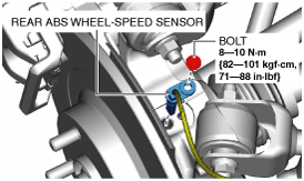
1. Remove the rear ABS wheel-speed sensor from the hub support.
amxuuw00005358
|
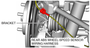
2. Remove the rear ABS wheel-speed sensor wiring harness from the bracket and set it aside so that it does not interfere with the servicing.
amxuuw00003429
|
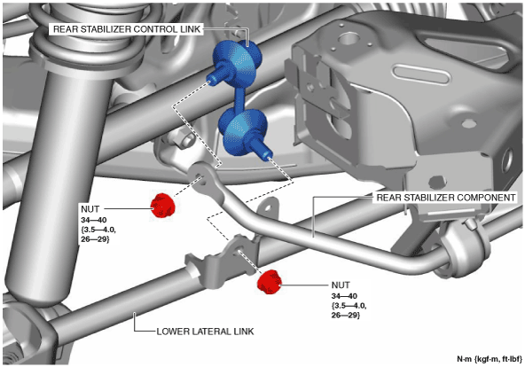
3. Remove the rear stabilizer control link.
amxuuw00003432
|
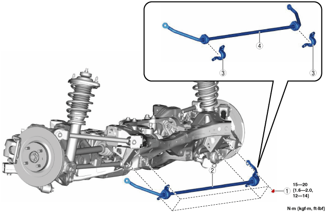
4. Remove in the order indicated in the table.
5. Install in the reverse order of removal.
amxuuw00003433
|
|
1
|
Nut
(See Nut Installation Note.)
|
|
2
|
Rear stabilizer component
|
|
3
|
Rear stabilizer bracket
|
|
4
|
Rear stabilizer
|
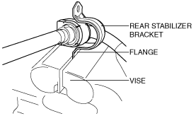
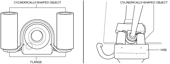
Rear Stabilizer Bracket Removal Note
1. If the rear stabilizer bracket cannot be removed by hand, remove it using a vise.
amxuuw00003434
|
Rear Stabilizer Bracket Installation Note
1. If the rear stabilizer bracket cannot be installed by hand, install it using a vise.
amxuuw00005359
|
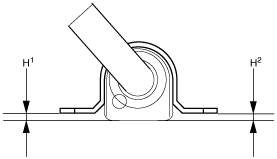
2. After installing the rear stabilizer bracket, verify that the positions of the rear stabilizer bracket and the rear stabilizer bushing are within the range shown in the figure.
amxuuw00005360
|
Rear Stabilizer Component Installation Note
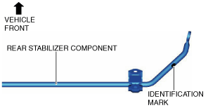
1. Assembly the rear stabilizer component so that the identification mark is on the right side of the vehicle.
amxuuw00003435
|
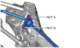
Nut Installation Note
1. Temporarily install nut A and B.
amxuuw00003436
|
2. Tighten bolt B.
3. Tighten bolt A.
4. Tighten bolt B.