 |
ardjjw00004803
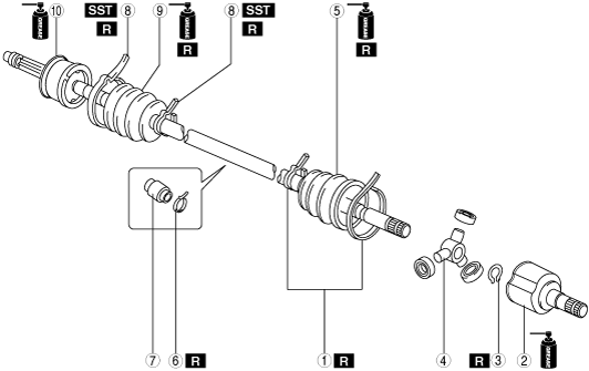
REAR DRIVE SHAFT DISASSEMBLY/ASSEMBLY [SKYACTIV-G 1.5, SKYACTIV-G 2.0 (SJ6A-EL)]
id0313001451x7
1. Disassemble in the order shown in the figure.
2. Assemble in the reverse order of disassembly.
ardjjw00004803
|
|
1
|
Boot band (differential side)
|
|
2
|
Outer ring
(See Outer Ring Disassembly Note.)
(See Outer Ring Assembly Note.)
|
|
3
|
Snap ring
|
|
4
|
Tripod joint
|
|
5
|
Boot (differential side)
|
|
6
|
Boot band (dynamic damper)
|
|
7
|
Dynamic damper
(See Dynamic Damper Assembly Note.)
|
|
8
|
Boot band (wheel side)
|
|
9
|
Boot (wheel side)
|
|
10
|
Shaft and ball joint component
|
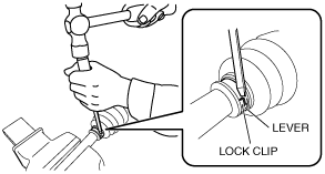
Boot Band (Differential Side) Disassembly Note
1. Using a flat chisel and hammer, lightly tap the lever of the boot band to disconnect the lock clip.
amxuuw00004758
|
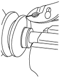
2. Remove the boot band using pliers.
aaxjjw00013154
|
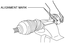
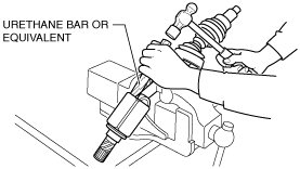
Outer Ring Disassembly Note
1. Place alignment marks on the shaft and outer ring.
amxuuw00004759
|
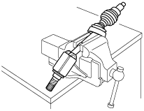
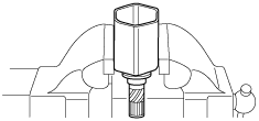
2. Secure the shaft in a vise.
aatjjw00009762
|
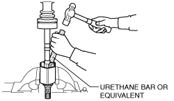
3. Lightly tap the outer ring evenly using a hammer and urethane bar or equivalent, and remove the outer ring from the shaft.
amxuuw00004760
|
4. Wipe off grease on the outer ring using a rag.
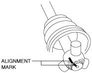
Snap Ring, Tripod Joint Disassembly Note
1. Place alignment marks on the shaft and tripod joint.
amxuuw00004761
|
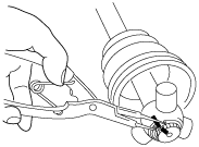
2. Remove the snap ring using snap ring pliers.
atstjw00000054
|
3. Remove the tripod joint from the shaft.
4. Wipe off grease on the shaft and tripod joint using a rag.
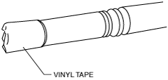
Boot (Differential Side) Disassembly Note
1. Wrap vinyl tape around the spline area of the shaft to prevent damage to the boot.
amxuuw00004762
|
2. Remove the boot (differential side).
3. Wipe off grease on the boot (differential side) using a rag.
Boot Band (Wheel Side) Disassembly Note
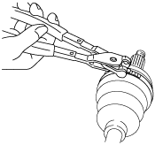
1. Remove the boot band using end clamp pliers.
aatjjw00009768
|
Boot (Wheel Side) Disassembly Note
1. Wrap vinyl tape around the spline area of the shaft to prevent damage to the boot.
amxuuw00004762
|
2. Remove the boot (wheel side).
3. Wipe off grease on the boot (wheel side) and ball joint using a rag.
Boot (Wheel Side) Assembly Note
1. Insert the shaft through the boot (wheel side) with the vinyl tape left wrapped around the spline area of the shaft.
2. Apply the specified grease to the ball joint and boot (wheel side).
Boot (wheel side) grease amount
|
Engine type |
Grease amount |
|---|---|
|
SKYACTIV-G 1.5
|
50—70 g {1.8—2.4 oz}
|
|
SKYACTIV-G 2.0
|
55—75 g {2.0—2.6 oz}
|
3. Assemble the boot (wheel side) to the ball joint.
Boot Band (Wheel Side) Assembly Note
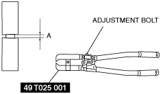
1. Adjust opening A of the SST to the standard by rotating the adjustment bolt.
amxuuw00004763
|
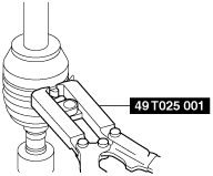
2. Crimp the boot band using the SST.
Large diameter side
atstjw00000047
|
Small diameter side
atstjw00000048
|
3. Verify that crimp B of the boot band is within the standard.
atstjw00000049
|
4. Verify that the boot band does not protrude from the band assembly area.
Dynamic Damper Assembly Note
1. Verify that the assembly position of the dynamic damper is within the standard.
amxuuw00004764
|
Boot (Differential Side) Assembly Note
1. Insert the shaft through the boot (differential side) with vinyl tape left wrapped around the spline area of the shaft.
2. Remove the vinyl tape wrapped around the spline of the shaft.
Tripod Joint, Snap Ring Assembly Note
1. Assemble the tripod joint with the shaft and tripod joint alignment marks aligned.
amxuuw00004761
|
2. Assemble a new snap ring using snap ring pliers.
atstjw00000054
|
3. Verify that the snap ring is assembled correctly in the groove of the shaft.
Outer Ring Assembly Note
1. Apply the specified grease to the outer ring and boot (differential side).
Boot (differential side) grease amount
|
Engine type |
Grease amount |
|---|---|
|
SKYACTIV-G 1.5 (SJ6A-EL)
|
80—100 g {2.9—3.5 oz}
|
|
SKYACTIV-G 1.5 (M66M-D)
|
75—95 g {2.7—3.3 oz}
|
|
SKYACTIV-G 2.0
|
95—115 g {3.4—4.0 oz}
|
2. Secure the outer ring in the vise.
aaxjjw00013191
|
3. After aligning the shaft and outer ring alignment marks, lightly tap the tripod joint area evenly using a hammer and urethane bar or equivalent, and insert the outer ring little by little while maintaining the shaft perpendicular.
amxuuw00004765
|
4. Assemble the boot (differential side) to the outer ring.
5. Set the drive shaft to the standard length.
Rear drive shaft (tripod joint) total length (standard)
|
Engine type |
Total length (standard) |
|
|---|---|---|
|
SKYACTIV-G 1.5
|
LH
|
794.7—804.7 mm {31.29—31.68 in}
|
|
RH
|
806.7—816.7 mm {31.76—32.15 in}
|
|
|
SKYACTIV-G 2.0
|
LH
|
789.1—799.1 mm {31.07—31.46 in}
|
|
RH
|
811.1—821.1 mm {31.94—32.32 in}
|
|
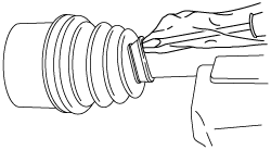
6. Release any trapped air from the boot by carefully lifting up the small end of the boot with a screwdriver wrapped in a clean rag.
aatjjw00009777
|
7. Verify that the drive shaft length is within the standard when the inside of the boot is at atmospheric pressure.
Boot Band (Differential Side) Assembly Note
1. Apply rust prevention oil to the inside of the boot band.
2. Lock the boot band against rotation using an appropriate tool as shown in the figure.
amxuuw00004766
|
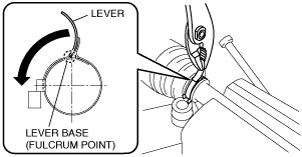
3. Using a pair of pliers, grip the lever at the base (fulcrum point) and rotate it in the direction of the arrow.
amxuuw00004767
|
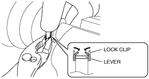
4. Hold the bent lever using a hand and secure it temporarily by pinching the lock clip using pliers.
amxuuw00004768
|
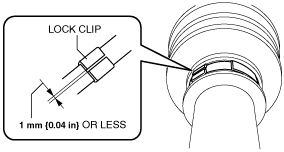
5. Lightly press the lock clip using a hammer so that the clearance of the lock clip is 1 mm {0.04 in} or less.
amxuuw00004769
|
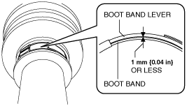
6. Verify that the clearance between the boot band and boot band lever is 1 mm {0.04 in} or less.
amxuuw00004770
|
7. After assembling the boot band, perform the following verification.