 |
amxzzn00000727
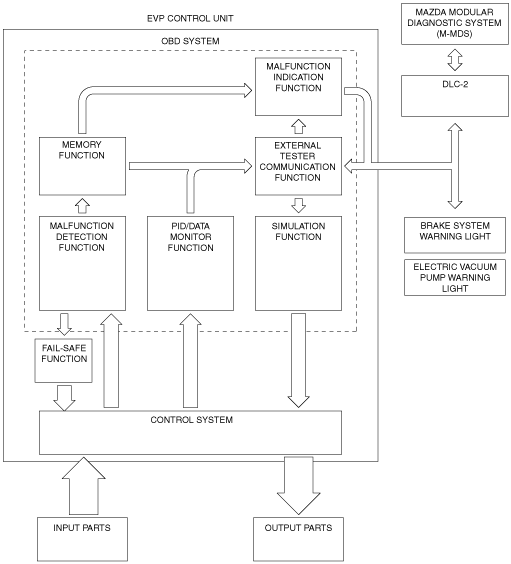
ON-BOARD DIAGNOSTIC SYSTEM [EVP CONTROL UNIT]
id040251836600
Outline
Block diagram
amxzzn00000727
|
Function
Malfunction detection function
Malfunction display function
Memory function
DTC table
|
DTC |
Brake system warning light*1 |
Electric vacuum pump warning light |
Description |
Fail-safe |
Drive cycle |
Self test type*2 |
Memory function |
|---|---|---|---|---|---|---|---|
|
C101A:00
|
Illuminated
|
Illuminated
|
Vacuum sensor 1/ Vacuum sensor 2 correlation problem
|
×
|
—
|
C, D
|
×
|
|
C101B:16
|
Not illuminated*3
|
Illuminated
|
Vacuum sensor 1 circuit low input
|
×
|
—
|
C, D
|
×
|
|
C101B:17
|
Not illuminated*3
|
Illuminated
|
Vacuum sensor 1 circuit high input
|
×
|
—
|
C, D
|
×
|
|
C101B:1C
|
Not illuminated*3
|
Illuminated
|
Vacuum sensor 1 power supply: low voltage/high voltage
|
×
|
—
|
C, D
|
×
|
|
C101C:00
|
Illuminated
|
Illuminated
|
Electric vacuum pump: open circuit in drive circuit
|
×
|
—
|
C, D
|
×
|
|
C101C:18
|
Illuminated
|
Illuminated
|
Electric vacuum pump: drive current decrease
|
×
|
—
|
C, D
|
×
|
|
C101C:71
|
Illuminated
|
Illuminated
|
Electric vacuum pump: stuck
|
×
|
—
|
C, D
|
×
|
|
C101C:72
|
Illuminated
|
Illuminated
|
Electric vacuum pump: logic inconsistent
|
×
|
—
|
C, D
|
×
|
|
C101C:73
|
Illuminated
|
Illuminated
|
Electric vacuum pump: short circuit in drive circuit
|
×
|
—
|
C, D
|
×
|
|
C1035:11
|
Illuminated
|
Illuminated
|
Electric vacuum pump relay 1: short to ground
|
×
|
—
|
C, D
|
×
|
|
C1035:12
|
Illuminated
|
Illuminated
|
Electric vacuum pump relay 1: short to power supply
|
×
|
—
|
C, D
|
×
|
|
C1035:13
|
Illuminated
|
Illuminated
|
Electric vacuum pump relay 1: stuck OFF
|
×
|
—
|
C, D
|
×
|
|
C1036:11
|
Illuminated
|
Illuminated
|
Electric vacuum pump relay 2: short to ground
|
×
|
—
|
C, D
|
×
|
|
C1036:12
|
Illuminated
|
Illuminated
|
Electric vacuum pump relay 2: short to power supply
|
×
|
—
|
C, D
|
×
|
|
C1036:13
|
Illuminated
|
Illuminated
|
Electric vacuum pump relay 2: stuck OFF
|
×
|
—
|
C, D
|
×
|
|
P050F:00
|
Illuminated
|
Illuminated
|
Low power brake unit vacuum
|
—
|
—
|
C
|
×
|
|
U0001:88
|
Not illuminated
|
Illuminated
|
CAN communication: module communication error
|
×
|
—
|
C
|
×
|
|
U0100:00
|
Not illuminated
|
Illuminated
|
CAN communication: communication error to PCM
|
×
|
—
|
C
|
×
|
|
U0100:08
|
Not illuminated
|
Illuminated
|
CAN communication: communication error to PCM
|
×
|
—
|
C
|
×
|
|
U0121:00
|
Not illuminated
|
Illuminated
|
CAN communication: communication error to DSC HU/CM
|
—
|
—
|
C
|
×
|
|
U0121:02
|
Not illuminated
|
Illuminated
|
CAN communication: communication error to DSC HU/CM
|
×
|
—
|
C
|
×
|
|
U0121:87
|
Not illuminated
|
Illuminated
|
CAN communication: communication error to DSC HU/CM
|
×
|
—
|
C
|
×
|
|
U0155:00
|
Not illuminated
|
Not illuminated
|
CAN communication: communication error to instrument cluster
|
—
|
—
|
C
|
×
|
|
U0401:00
|
Not illuminated*3
|
Illuminated
|
CAN communication: signal error from PCM
|
×
|
—
|
C
|
×
|
|
U0401:86
|
Not illuminated*3
|
Illuminated
|
CAN communication: signal error from PCM
|
×
|
—
|
C
|
×
|
|
U0415:00
|
Not illuminated
|
Illuminated
|
CAN communication: signal error from DSC HU/CM
|
—
|
—
|
C
|
×
|
|
U0415:29
|
Not illuminated
|
Illuminated
|
CAN communication: signal error from DSC HU/CM
|
×
|
—
|
C
|
×
|
|
U0415:86
|
Not illuminated
|
Illuminated
|
CAN communication: signal error from DSC HU/CM
|
×
|
—
|
C
|
×
|
|
U3000:11
|
Illuminated
|
Illuminated
|
EVP control unit internal circuit malfunction
|
×
|
—
|
C, D
|
×
|
|
U3000:12
|
Illuminated
|
Illuminated
|
EVP control unit internal circuit malfunction
|
×
|
—
|
C, D
|
×
|
|
U3000:46
|
Illuminated
|
Illuminated
|
EVP control unit internal circuit malfunction
|
×
|
—
|
C, D
|
×
|
|
U3000:47
|
Illuminated
|
Illuminated
|
EVP control unit internal circuit malfunction
|
×
|
—
|
C, D
|
×
|
|
U3000:4B
|
Illuminated
|
Illuminated
|
EVP control unit: High internal temperature
|
×
|
—
|
C, D
|
×
|
|
U3000:56
|
Illuminated
|
Illuminated
|
EVP control unit internal circuit malfunction
|
×
|
—
|
C, D
|
×
|
|
U3000:63
|
Illuminated
|
Illuminated
|
Electric vacuum pump control unit: long period of operation
|
×
|
—
|
C
|
×
|
|
U3000:96
|
Illuminated
|
Illuminated
|
EVP control unit internal circuit malfunction
|
×
|
—
|
C, D
|
×
|
|
U3003:16
|
Illuminated
|
Illuminated
|
EVP control unit power supply low input
|
×
|
—
|
C
|
×
|
|
U3003:17
|
Illuminated
|
Illuminated
|
EVP control unit power supply high input
|
×
|
—
|
C
|
×
|
DTC detection logic and conditions table
|
DTC |
Condition |
Detection conditionl |
|---|---|---|
|
C101A:00
|
Vacuum sensor 1/ Vacuum sensor 2 correlation problem
|
• Vacuum sensor 1 and 2 values are compared and the difference is 5 kPa {38 mmHg, 2 inHg} or more for a continuous 1 s.
|
|
C101B:16
|
Vacuum sensor 1 circuit low input
|
• If the EVP control unit detects that the vacuum sensor 1 voltage at the EVP control unit terminal AC is below 0.16 V for 0.6 s, the EVP control unit determines that the vacuum sensor 1 circuit has a malfunction.
|
|
C101B:17
|
Vacuum sensor 1 circuit high input
|
• If the EVP control unit detects that the vacuum sensor 1 voltage at the EVP control unit terminal AC is above 4.9 V for 0.6 s, the EVP control unit determines that the vacuum sensor 1 circuit has a malfunction.
|
|
C101B:1C
|
Vacuum sensor 1 power supply: low voltage/high voltage
|
• Power supply voltage for vacuum sensor 1 deviates from 4.5 V to 5.5 V for a continuous 0.55 s.
|
|
C101C:00
|
Electric vacuum pump: open circuit in drive circuit
|
• An open circuit in the motor drive circuit of the electric vacuum pump occurs for a continuous 0.2 s when the electric vacuum pump is stopped.
|
|
C101C:18
|
Electric vacuum pump: drive current decrease
|
• Electric vacuum pump drive circuit electrical current is low for a continuous 3 s when the electric vacuum pump is operated.
|
|
C101C:71
|
Electric vacuum pump: stuck
|
• Electric vacuum pump drive circuit electrical current is high for a continuous 3 s when the electric vacuum pump is operated.
|
|
C101C:72
|
Electric vacuum pump: logic inconsistent
|
• Control status and the PID value of electric vacuum pump relay 1 or 2 (built into EVP control unit) do not correspond for a continuous 0.2 s.
|
|
C101C:73
|
Electric vacuum pump: short circuit in drive circuit
|
• Resistance of the electric vacuum pump drive circuit is less than 10 m ohm.
|
|
C1035:11
|
Electric vacuum pump relay 1: short to ground
|
• Resistance between the EVP control unit terminal C circuit and ground is less than 10 m ohm.
|
|
C1035:12
|
Electric vacuum pump relay 1: short to power supply
|
• EVP control unit terminal C voltage is 90% or more of the battery voltage for a continuous 0.5 s when electric vacuum pump relay 1 is turned off.
|
|
C1035:13
|
Electric vacuum pump relay 1: stuck OFF
|
• EVP control unit terminal C voltage deviates from the 90% to 110% battery voltage range for a continuous 0.2 s when electric vacuum pump relay 1 is turned on.
|
|
C1036:11
|
Electric vacuum pump relay 2: short to ground
|
• EVP control unit terminal E voltage is less than 1 V for a continuous 0.5 s when electric vacuum pump relay 2 is turned off.
|
|
C1036:12
|
Electric vacuum pump relay 2: short to power supply
|
• EVP control unit terminal E voltage of 2 V or more is detected when the electric vacuum pump is operated.
|
|
C1036:13
|
Electric vacuum pump relay 2: stuck OFF
|
• EVP control unit terminal E voltage is 1 V or more for a continuous 0.2 s when electric vacuum pump relay 2 is turned on.
|
|
P050F:00
|
Low power brake unit vacuum
|
• Power brake unit vacuum is 30 kPa {225 mmHg, 8.8 inHg} lower or more than the barometric pressure for a continuous 15 s when the electric vacuum pump is operating.
|
|
U0001:88
|
CAN communication: module communication error
|
• Open or short circuit in CAN system wiring harness for a continuous 1.4 s.
|
|
U0100:00
|
CAN communication: communication error to PCM
|
• Engine speed signal via CAN communication cannot be received from the PCM for a continuous 5 s.
|
|
U0100:08
|
CAN communication: communication error to PCM
|
• Vacuum sensor 2 signal via CAN communication cannot be received from the PCM for a continuous 5 s.
|
|
U0121:00
|
CAN communication: communication error to DSC HU/CM
|
• CAN communication from the DSC HU/CM is interrupted for a continuous 5 s.
|
|
U0121:02
|
CAN communication: communication error to DSC HU/CM
|
• Brake fluid pressure signal via CAN communication cannot be received from the PCM for a continuous 5 s.
|
|
U0121:87
|
CAN communication: communication error to DSC HU/CM
|
• Vehicle speed signal via CAN communication cannot be received from the DSC HU/CM for a continuous 5 s.
|
|
U0155:00
|
CAN communication: communication error to instrument cluster
|
• CAN communication from the instrument cluster is interrupted for a continuous 5 s.
|
|
U0401:00
|
CAN communication: signal error from PCM
|
• Vacuum sensor 2 signal from the PCM is invalid or not within range for a continuous 1 s.
|
|
U0401:86
|
CAN communication: signal error from PCM
|
• Engine speed signal error from the PCM continues for 5 s.
|
|
U0415:00
|
CAN communication: signal error from DSC HU/CM
|
• Signal from the DSC HU/CM is not received for 5 s.
|
|
U0415:29
|
CAN communication: signal error from DSC HU/CM
|
• Brake fluid pressure error from the DSC HU/CM continues for 1 s.
|
|
U0415:86
|
CAN communication: signal error from DSC HU/CM
|
• Vehicle speed signal error from the DSC HU/CM continues for 5 s.
|
|
U3000:11
|
EVP control unit internal circuit malfunction
|
• Open or short to ground in the temperature sensor circuit inside the EVP control unit continues for 0.1 s.
|
|
U3000:12
|
EVP control unit internal circuit malfunction
|
• Short to power supply in the temperature sensor inside the EVP control unit continues for 0.1 s.
|
|
U3000:46
|
EVP control unit internal circuit malfunction
|
• ROM/RAM data error in the electric vacuum pump is detected.
|
|
U3000:47
|
EVP control unit internal circuit malfunction
|
• Sub CPU/ROM/RAM error in the EVP control unit is detected.
|
|
U3000:4B
|
EVP control unit: High internal temperature
|
• A circuit board temperature inside the EVP control unit of 130 degrees C {266 degrees F} or more is detected.
|
|
U3000:56
|
EVP control unit internal circuit malfunction
|
• ROM/RAM file error in the EVP control unit is detected.
|
|
U3000:63
|
Electric vacuum pump control unit: long period of operation
|
• The electric vacuum pump is used continuously for 180 s or more.
|
|
U3000:96
|
EVP control unit internal circuit malfunction
|
• The A/D converter in the electric vacuum pump unit or the current value of the pump control circuit when the electric vacuum pump is stopped is stuck for a continuous 0.2 s.
|
|
U3003:16
|
EVP control unit power supply low input
|
• The power supply voltage for the EVP control unit is 8.3 V or less for a continuous 0.1 s.
|
|
U3003:17
|
EVP control unit power supply high input
|
• The power supply voltage for the EVP control unit is 17.4 V or more for a continuous 0.1 s.
|
Status byte for DTC
am2zzn00002656
|
Fail-safe function
Fail-safe function table
|
DTC |
Fail-safe function |
|---|---|
|
C101A:00
|
Permits control to drive the motor regularly
|
|
C101B:16
|
Calculates power brake unit vacuum using only vacuum sensor 2 signal, and controls electric vacuum pump
|
|
C101B:17
|
Calculates power brake unit vacuum using only vacuum sensor 2 signal, and controls electric vacuum pump
|
|
C101B:1C
|
Calculates power brake unit vacuum using only vacuum sensor 2 signal, and controls electric vacuum pump
|
|
C101C:00
|
Inhibits electric vacuum pump operation, and DSC HU/CM performs vacuum booster fail support
|
|
C101C:18
|
Inhibits electric vacuum pump operation, and DSC HU/CM performs vacuum booster fail support
|
|
C101C:71
|
Inhibits electric vacuum pump operation, and DSC HU/CM performs vacuum booster fail support
|
|
C101C:72
|
Inhibits electric vacuum pump operation, and DSC HU/CM performs vacuum booster fail support
|
|
C101C:73
|
Inhibits electric vacuum pump operation, and DSC HU/CM performs vacuum booster fail support
|
|
C1035:11
|
Inhibits electric vacuum pump operation, and DSC HU/CM performs vacuum booster fail support
|
|
C1035:12
|
Inhibits electric vacuum pump operation, and DSC HU/CM performs vacuum booster fail support
|
|
C1035:13
|
Inhibits electric vacuum pump operation, and DSC HU/CM performs vacuum booster fail support
|
|
C1036:11
|
Inhibits electric vacuum pump operation, and DSC HU/CM performs vacuum booster fail support
|
|
C1036:12
|
Inhibits electric vacuum pump operation, and DSC HU/CM performs vacuum booster fail support
|
|
C1036:13
|
Inhibits electric vacuum pump operation, and DSC HU/CM performs vacuum booster fail support
|
|
P050F:00
|
—
|
|
U0001:88
|
Inhibits electric vacuum pump operation, and DSC HU/CM performs vacuum booster fail support
|
|
U0100:00
|
Performs control of electric vacuum pump under engine operation condition of engine running
|
|
U0100:08
|
Calculates power brake unit vacuum using only vacuum sensor 1 signal only, and controls electric vacuum pump
|
|
U0121:00
|
—
|
|
U0121:02
|
Controls electric vacuum pump without using brake fluid pressure.
|
|
U0121:87
|
Sets vehicle speed and controls electric vacuum pump.
|
|
U0155:00
|
—
|
|
U0401:00
|
Calculates power brake unit vacuum using only vacuum sensor 1 signal only, and controls electric vacuum pump
|
|
U0401:86
|
Performs control of electric vacuum pump under engine operation condition of engine running
|
|
U0415:00
|
—
|
|
U0415:29
|
Controls electric vacuum pump without using brake fluid pressure.
|
|
U0415:86
|
Sets vehicle speed and controls electric vacuum pump.
|
|
U3000:11
|
Inhibits electric vacuum pump operation, and DSC HU/CM performs vacuum booster fail support
|
|
U3000:12
|
Inhibits electric vacuum pump operation, and DSC HU/CM performs vacuum booster fail support
|
|
U3000:46
|
Inhibits electric vacuum pump operation, and DSC HU/CM performs vacuum booster fail support
|
|
U3000:47
|
Inhibits electric vacuum pump operation, and DSC HU/CM performs vacuum booster fail support
|
|
U3000:4B
|
Inhibits electric vacuum pump operation, and DSC HU/CM performs vacuum booster fail support
|
|
U3000:56
|
Inhibits electric vacuum pump operation, and DSC HU/CM performs vacuum booster fail support
|
|
U3000:63
|
Inhibits electric vacuum pump operation, and DSC HU/CM performs vacuum booster fail support
|
|
U3000:96
|
Inhibits electric vacuum pump operation, and DSC HU/CM performs vacuum booster fail support
|
|
U3003:16
|
Inhibits electric vacuum pump operation, and DSC HU/CM performs vacuum booster fail support
|
|
U3003:17
|
Inhibits electric vacuum pump operation, and DSC HU/CM performs vacuum booster fail support
|
Snapshot data
|
Snapshot data item |
Unit |
Definition |
Data read/use method |
Corresponding data monitor items |
|---|---|---|---|---|
|
AAT
|
°C, °F
|
Ambient air temperature
|
—
|
—
|
|
APP_STATUS
|
Accelerator Pedal Off/
Under 20%/
Over 20%/
FAIL
|
Accelerator pedal position
|
—
|
—
|
|
BRK_SIG
|
Off/On
|
Brake pedal signal
|
—
|
BRK_SIG
|
|
CFG_STATUS
|
Config Complete/
Not Configured/
Config Error
|
Configuration status
|
—
|
—
|
|
ECT_STATUS
|
Under 0 degrees C/
0 - Under 80 degrees C/
Over 80 degrees C/
FAIL
|
Engine coolant temperature status
|
—
|
—
|
|
ECU_TEMP
|
°C, °F
|
ECU internal temperature
|
—
|
ECU_TEMP
|
|
IC_VPWR
|
V
|
Instrument cluster power supply
|
• The EVP control unit constantly receives the power supply voltage value of the instrument cluster sent via CAN signal from the instrument cluster.
• If a DTC is detected, the EVP control unit records the power supply voltage of the instrument cluster when the DTC was detected, and it is displayed in the M-MDS.
|
—
|
|
IG-ON_TIMER
|
hh:mm:ss*1
|
Elapsed time since ignition was switched ON
|
• The EVP control unit constantly receives the elapsed time since the ignition was switched ON sent via CAN signal from the instrument cluster.
• If a DTC is detected, the EVP control unit records the elapsed time since the ignition was switched ON when the DTC was detected, and it is displayed in the M-MDS.
|
—
|
|
PWR_MODE_KEY
|
Key Out/Key Recently Out/Key Approved (Position 0)/Post Accessory (Position 0)/Accessory (Position 1)/Post Ignition (Position 1)/Ignition On (Position 2)/Running (Position 2)/Running - Starting In Progress (Position 2)/Crank (Position 3)
|
• Key Out: Ignition switched off
• Key Recently Out (Position 0): Elapsed time within 3 s since ignition was switched off
• Accessory (Position 1): Ignition is switched to ACC
• Post Ignition (Position 2): Elapsed time within 3 s since ignition was switched ON
• Ignition On (Position 2): Ignition switched ON (engine off)
• Running (Position 2): Ignition switched ON (engine on)
• Running - Starting: Cranking condition
|
• The EVP control unit constantly receives the ignition switch status sent via CAN signal from the instrument cluster.
• If a DTC is detected, the EVP control unit records the ignition switch status when the DTC was detected, and it is displayed in the M-MDS.
|
—
|
|
RPM_STATUS
|
Engine Stop/
Under 1500 rpm/
Over 1500 rpm/
FAIL
|
Engine RPM status
|
• The EVP control unit constantly receives the ignition switch status sent via CAN signal from the instrument cluster.
• If a DTC is detected, the EVP control unit records the ignition switch status when the DTC was detected, and it is displayed in the M-MDS.
|
—
|
|
SHIFT_STATUS
|
P/N
D/
R/
FAIL
|
Shift position status
|
• The EVP control unit constantly receives the selector lever position sent via CAN signal from the instrument cluster.
• If a DTC is detected, the EVP control unit records the selector lever position when the DTC was detected, and it is displayed in the M-MDS.
|
—
|
|
TOTAL_DIST
|
km, ft, mi
|
Accumulated total traveled distance from completion of vehicle until EVP control unit detects DTC (Odometer value in instrument cluster)
|
The distance traveled when the EVP control unit detected a DTC can be calculated by performing the following procedure.
1. Verify the odometer value in the instrument cluster.
2. Verify the snap shot data item TOTAL_DIST.
3. Subtract 2 from 1.
|
—
|
|
TOTAL_TIME
|
hh:mm:ss*1
|
Accumulated total elapsed time since vehicle completion until EVP control unit detects a DTC
|
The elapsed time when the EVP control unit detected a DTC can be calculated by performing the following procedure.
1. Verify the PID item TOTAL_TIME of the instrument cluster.
2. Verify the snap shot data item TOTAL_TIME.
3. Subtract 2 from 1.
|
—
|
|
VP_C
|
A
|
Electric vacuum pump operation current
|
—
|
VP_C
|
|
VP_MV
|
V
|
Electric vacuum pump terminal voltage (-)
|
—
|
VP_MV
|
|
VP_PV
|
V
|
Electric vacuum pump terminal voltage (+)
|
—
|
VP_PV
|
|
VPD_THR
|
kPa, mmHg, inHg
|
Electric vacuum pump deactivation threshold
• If the power brake unit vacuum is larger than the value which is calculated by subtracting VPD_THR from barometric pressure, the electric vacuum pump is deactivated
|
—
|
VPD_THR
|
|
VPR1_V
|
Off/On
|
Electric vacuum pump relay 1 status
|
—
|
VPR1_V
|
|
VPR2_V
|
Off/On
|
Electric vacuum pump relay 2 status
|
—
|
VPR2_V
|
|
VPWR
|
V
|
Power supply
|
—
|
VPWR
|
|
VS1
|
kPa, mmHg, inHg
|
Power brake unit vacuum (absolute pressure) detected by vacuum sensor 1
|
—
|
VS1
|
|
VS1_V
|
V
|
Vacuum sensor 1 power supply
|
—
|
VS1_V
|
|
VS2
|
kPa, mmHg, inHg
|
Power brake unit vacuum (absolute pressure) detected by vacuum sensor 2
|
—
|
VS2
|
|
VSPD_STATUS
|
Stop/
0 - 10 km/h/
Over 10 km/h/
FAIL
|
Vehicle speed status
|
• The EVP control unit constantly receives the vehicle speed sent via CAN signal from the instrument cluster.
• If a DTC is detected, the EVP control unit records the vehicle speed when the DTC was detected, and it is displayed in the M-MDS.
|
—
|
PID/data monitor function
|
Monitor item |
Unit/operation |
Definition |
|---|---|---|
|
BRK_SIG
|
Off/On
|
Brake pedal signal
|
|
ECU_TEMP
|
°C, °F
|
ECU internal temperature
|
|
VP_C
|
A
|
Electric vacuum pump operation current
|
|
VP_MV
|
V
|
Electric vacuum pump terminal voltage (-)
|
|
VP_PV
|
V
|
Electric vacuum pump terminal voltage (+)
|
|
VPD_THR
|
—
|
Electric vacuum pump deactivation threshold
• If the power brake unit vacuum is larger than the value which is calculated by subtracting VPD_THR from barometric pressure, the electric vacuum pump is deactivated
|
|
VPR1_V
|
Off/On
|
Electric vacuum pump relay 1 status
|
|
VPR2_V
|
Off/On
|
Electric vacuum pump relay 2 status
|
|
VPS_FBK
|
Off/On
|
Electric vacuum pump operation status (feedback value)
|
|
VPWR
|
V
|
Power supply
|
|
VS1
|
Pa, mmHg, inHg
|
Power brake unit vacuum (absolute pressure) detected by vacuum sensor 1
|
|
VS1_INP_STAT
|
—
|
Vacuum sensor 1 input status
|
|
VS1_V
|
V
|
Vacuum sensor 1 power supply
|
|
VS2
|
Pa, mmHg, inHg
|
Power brake unit vacuum (absolute pressure) detected by vacuum sensor 2
|
Simulation function
|
Simulation item |
Operation |
Output part |
Operating condition |
|---|---|---|---|
|
VPS_FBK
|
Off/On
|
Electric vacuum pump
|
For maximum of 30 s when all of the following conditions are met with ignition switched ON (engine off or on)
• Vehicle speed 6 km/h {3 mph} or less
• Operation of electric vacuum pump not inhibited by fail-safe
|
External tester communication function
|
Diagnostic function name |
Signal received |
Signal sent |
|---|---|---|
|
Malfunction detection function
|
DTC verification signal
|
DTC(s)
|
|
PID/data monitor function
|
Command signal to read selected monitor item
|
Monitored data for requested monitor item
|
|
Simulation function
|
Operation command signal for selected simulation item
|
Output part drive signal
|
