 |
amxzzw00003685
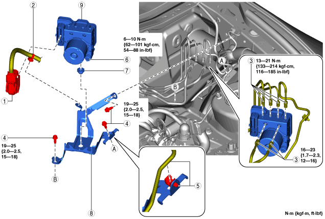
DSC HU/CM REMOVAL/INSTALLATION [R.H.D.]
id0415008010b5
1. Disconnect the negative battery cable. (See NEGATIVE BATTERY CABLE DISCONNECTION/CONNECTION.)
2. Remove in the order indicated in the table.
3. Install in the reverse order of removal.
4. After installation, add brake fluid, bleed the air, and inspect for fluid leakage. (See BRAKE FLUID AIR BLEEDING.)
5. If the DSC HU/CM is replaced, perform the auto configuration and the initialization of the sensors for DSC-related parts.
amxzzw00003685
|
|
1
|
DSC HU/CM Connector
|
|
2
|
Wiring harness clip
|
|
3
|
Brake pipe
(See Brake Pipe Removal Note.)
(See Brake Pipe Installation Note.)
|
|
4
|
Bolt
(See Bolt Installation Note.)
|
|
5
|
Clip, Brake pipe
|
|
6
|
Nut
|
|
7
|
Mount rubber
|
|
8
|
Bracket
|
|
9
|
DSC HU/CM
|
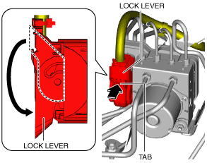
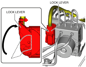
DSC HU/CM Connector Removal Note
1. Pull the lock lever down in the direction of the arrow while pressing the tab of the lock lever.
amxzzw00003686
|
2. Disconnect the DSC HU/CM connector.
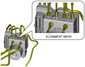
Brake Pipe Removal Note
1. Place an alignment marks on the brake pipe and DSC HU/CM.
amxzzw00003687
|
2. Apply protective tape to the connector to prevent brake fluid from entering.
3. Disconnect the brake pipes.
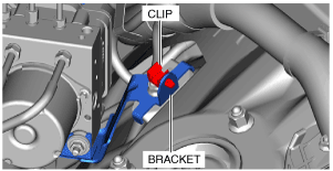
Clip, Brake Pipe Installation Note
1. Install the clip as shown in the figure.
amxzzw00003688
|
2. Install the brake pipe to the clip.
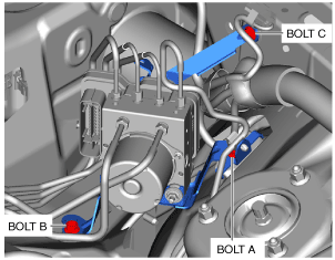
Bolt Installation Note
1. Tighten the bolt A to the specified torque.
amxzzw00003689
|
2. Tighten the bolt B to the specified torque.
3. Tighten the bolt C to the specified torque.
Brake Pipe Installation Note
1. Align the marks made before removal and install the brake pipe to the DSC HU/CM and brake pipe joint referring to the figure.
amxzzw00003690
|
DSC HU/CM Connector Installation Note
1. Connect the connector and pull the lock lever up in the direction of the arrow.
amxzzw00003691
|
2. After connecting the connector, verify that the connector cover is completely pushed in.