|
1
|
RECORD VEHICLE STATUS WHEN DTC WAS DETECTED TO UTILIZE WITH REPEATABILITY VERIFICATION
-
Note
-
• Recording can be facilitated using the screen capture of the PC function.
• Record the freeze frame data/snap shot data.
|
—
|
Go to the next step.
|
|
2
|
VERIFY RELATED SERVICE INFORMATION AVAILABILITY
• Verify related Service Information availability.
• Is any related Service Information available?
|
Yes
|
Perform repair or diagnosis according to the available Service Information.
• If the vehicle is not repaired, go to the next step.
|
|
No
|
Go to the next step.
|
|
3
|
INSPECT/ADJUST TR SWITCH
• Is there a malfunction in the TR switch?
|
Yes
|
Adjust the TR switch, then go to Step 13.
|
|
No
|
Go to the next step.
|
|
4
|
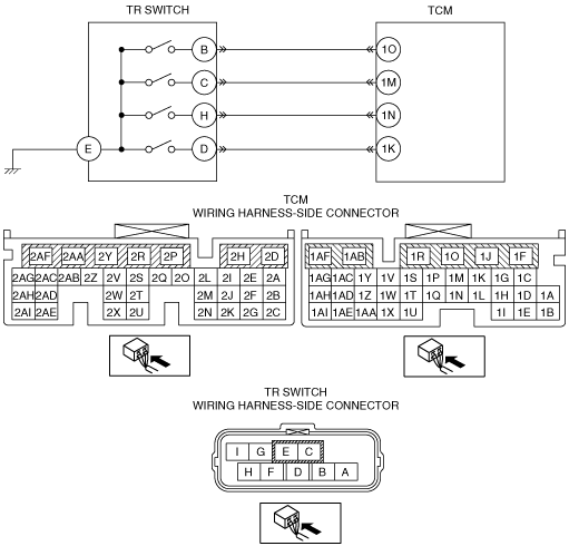
INSPECT TR SWITCH CIRCUIT
• Connect the TCM connector.
• Switch the ignition ON. (engine off)
• Inspect the voltage between TCM terminal (wiring harness-side) and body ground.
-
― TCM terminal 1O
-
• P position: 0 V
• Other position: B+
― TCM terminal 1M
-
• R position: 0 V
• Other position: B+
― TCM terminal 1N
-
• N position: 0 V
• Other position: B+
― TCM terminal 1K
-
• D position: 0 V
• Other position: B+
• Are any of following terminal voltage turned on for even a moment while shifting selector lever slowly from P to D position?
|
Yes
|
Go to Step 13.
|
|
No
|
Go to the next step.
|
|
5
|
INSPECT TR SWITCH CIRCUIT
• Are all terminal voltage 0 V in Step 3?
|
Yes
|
Go to Step 10.
|
|
No
|
Go to the next step.
|
|
6
|
INSPECT TR SWITCH CIRCUIT
• Are there two or more terminals where the voltage is abnormal in Step 3?
|
Yes
|
Adjust the TR switch, then go to Step 13.
|
|
No
|
Go to the next step.
|
|
7
|
INSPECT TCM CONNECTOR FOR POOR CONNECTION
• Switch the ignition off.
• Disconnect the TCM connector.
• Inspect for poor connection at TCM terminals 1O, 1K, 1M and 1N (such as damaged/pulled-out pins, corrosion).
• Is there any malfunction?
|
Yes
|
Repair or replace the connector and/or terminal, then go to Step 13.
|
|
No
|
Go to the next step.
|
|
8
|
INSPECT TR SWITCH CONNECTOR FOR POOR CONNECTION
• Disconnect the TR switch connector.
• Inspect for poor connection at TR switch terminals B, C, D and H (part-side) (such as damaged/pulled-out pins, corrosion)
• Are TR switch terminals normal?
|
Yes
|
Go to the next step.
|
|
No
|
Repair terminals or replace the TR switch, then go to Step 13.
|
|
9
|
INSPECT TR SWITCH
• Is the TR switch normal?
|
Yes
|
Repair or replace the wiring harness for open circuit, then go to Step 13.
|
|
No
|
Replace the TR switch, then go to Step 13.
|
|
10
|
INSPECT TR SWITCH GROUND CIRCUIT FOR OPEN CIRCUIT
• Switch the ignition off.
• Disconnect the TR switch connector.
• Switch the ignition ON (engine off).
• Inspect for continuity between TR switch terminal E (wiring harness-side) and body ground.
• Is there continuity?
|
Yes
|
Go to the next step.
|
|
No
|
Refer to the wiring diagram and verify whether or not there is a common connector between TR switch terminal E and body ground.
If there is a common connector:
• Determine the malfunctioning part by inspecting the common connector and the terminal for corrosion, damage, or pin disconnection, and the common wiring harness for an open circuit.
• Repair or replace the malfunctioning part.
If there is no common connector:
• Repair or replace the wiring harness which has an open circuit.
Go to Step 13.
|
|
11
|
INSPECT TR SWITCH CONNECTOR FOR POOR CONNECTION
• Disconnect the TR switch connector.
• Inspect for poor connection at TR switch terminal E (part-side) (such as damaged/pulled-out pins, corrosion)
• Are TR switch terminals normal?
|
Yes
|
Go to the next step.
|
|
No
|
Repair terminals or replace the TR switch, then go to Step 13.
|
|
12
|
INSPECT TR SWITCH
• Is the TR switch normal?
|
Yes
|
Go to the next step.
|
|
No
|
Replace the TR switch, then go to the next step.
|
|
13
|
VERIFY SAME DTC IS NOT PRESENT
• Always reconnect all disconnected connectors.
• Clear the DTC using the M-MDS.
• Perform the following procedure to ensure that the DTC has been resolved:
-
1. Start the engine.
2. Warm-up the engine to normal operating temperature.
3. Depress the brake pedal, and shift the selector lever from P to D for 2 s or more.
4. Gradually slow down and stop the vehicle.
5. Switch the ignition off.
6. Start the engine.
7. Depress the brake pedal, and shift the selector lever from P to D for 2 s or more.
• Perform the DTC inspection using the M-MDS.
• Is the same DTC present?
|
Yes
|
Replace the TCM, then go to the next step.
|
|
No
|
Go to the next step.
|
|
14
|
VERIFY DTC TROUBLESHOOTING COMPLETED
• Clear the DTC using the M-MDS.
• Perform the DTC inspection using the M-MDS.
• Are any DTCs present?
|
Yes
|
Go to the applicable DTC inspection.
|
|
No
|
DTC troubleshooting completed.
|