|
1
|
RECORD VEHICLE STATUS WHEN DTC WAS DETECTED TO UTILIZE WITH REPEATABILITY VERIFICATION
-
Note
-
• Recording can be facilitated using the screen capture function of the PC.
• Record the freeze frame data/snap shot data.
|
—
|
Go to the next step.
|
|
2
|
VERIFY RELATED SERVICE INFORMATION AVAILABILITY
• Verify related Service Information availability.
• Is any related Service Information available?
|
Yes
|
Perform repair or diagnosis according to the available Service Information.
• If the vehicle is not repaired, go to the next step.
|
|
No
|
Go to the next step.
|
|
3
|
INSPECT FOR SHORT TO GROUND IN ELECTRIC AT OIL PUMP CIRCUIT
• Disconnect the TCM connector.
• Inspect for continuity between the following terminals (vehicle wiring harness side) and body ground.
-
― Electric AT oil pump terminal A
― Electric AT oil pump terminal B
― Electric AT oil pump terminal C
• Is there continuity?
|
Yes
|
Refer to the wiring diagram and verify if there is a common connector between the following terminals.
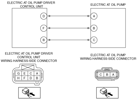
• Electric AT oil pump terminal A and electric AT oil pump driver control unit terminal D
• Electric AT oil pump terminal B and electric AT oil pump driver control unit terminal F
• Electric AT oil pump terminal C and electric AT oil pump driver control unit terminal B
If there is a common connector:
• Inspect the common connector and terminals for corrosion, damage, or disconnection and the common wiring harnesses for short to ground to determine the malfunctioning location.
• Repair or replace the malfunctioning location.
If there is no common connector:
• Repair or replace the wiring harness which is shorted to ground.
Go to Step 10.
|
|
No
|
Go to the next step.
|
|
4
|
INSPECT FOR SHORT TO POWER SUPPLY IN ELECTRIC AT OIL PUMP DRIVER CONTROL UNIT CIRCUIT
• Connect the TCM connector.
• Start the engine.
• Measure the voltage between the following terminals (vehicle wiring harness side) and body ground before/after operating i-stop.
-
― Electric AT oil pump terminal A
― Electric AT oil pump terminal B
― Electric AT oil pump terminal C
• Is the voltage B+ constantly?
|
Yes
|
Refer to the wiring diagram and verify if there is a common connector between the following terminals.
• Electric AT oil pump terminal A and electric AT oil pump driver control unit terminal D
• Electric AT oil pump terminal B and electric AT oil pump driver control unit terminal F
• Electric AT oil pump terminal C and electric AT oil pump driver control unit terminal B
If there is a common connector:
• Inspect the common connector and terminals for corrosion, damage, or disconnection and the common wiring harnesses for short to power supply to determine the malfunctioning location.
• Repair or replace the malfunctioning location.
If there is no common connector:
• Repair or replace the wiring harness which is shorted to the power supply.
Go to Step 10.
|
|
No
|
Go to the next step.
|
|
5
|
INSPECT ELECTRIC AT OIL PUMP DRIVER CONTROL UNIT FOR OPEN CIRCUIT
• Disconnect the TCM connector.
• Disconnect the electric AT oil pump driver control unit connector.
• Inspect the wiring harness for continuity between the following terminals (vehicle wiring harness side).
-
― Electric AT oil pump terminal A and electric AT oil pump driver control unit terminal D
― Electric AT oil pump terminal B and electric AT oil pump driver control unit terminal F
― Electric AT oil pump terminal C and electric AT oil pump driver control unit terminal B
• Is there continuity?
|
Yes
|
Go to the next step.
|
|
No
|
Refer to the wiring diagram and verify if there is a common connector between the following terminals.
• Electric AT oil pump terminal A and electric AT oil pump driver control unit terminal D
• Electric AT oil pump terminal B and electric AT oil pump driver control unit terminal F
• Electric AT oil pump terminal C and electric AT oil pump driver control unit terminal B
If there is a common connector:
• Inspect the common connector and terminals for corrosion, damage, or disconnection and the common wiring harnesses for an open circuit to determine the malfunctioning location.
• Repair or replace the malfunctioning location.
If there is no common connector:
• Repair or replace the wiring harness which has an open circuit.
Go to Step 10.
|
|
6
|
INSPECT ELECTRIC AT OIL PUMP DRIVER CONTROL UNIT CONNECTOR
• Switch the ignition off.
• Disconnect the electric AT oil pump driver control unit connector.
• Inspect the connector engagement and connection condition, and inspect the terminals for damage, deformation, corrosion, or disconnection.
• Is there any malfunctioning location?
|
Yes
|
Repair or replace the connector/terminal, then go to Step 10.
|
|
No
|
Go to the next step.
|
|
7
|
INSPECT ELECTRIC AT OIL PUMP CONNECTOR
• Switch the ignition off.
• Disconnect the electric AT oil pump connector.
• Inspect the connector engagement and connection condition, and inspect the terminals for damage, deformation, corrosion, or disconnection.
• Is there any malfunctioning location?
|
Yes
|
Repair or replace the connector/terminal, then go to Step 10.
|
|
No
|
Go to the next step.
|
|
8
|
INSPECT ELECTRIC AT OIL PUMP DRIVER CONTROL UNIT
• Inspect the electric AT oil pump driver control unit.
• Is the electric AT oil pump driver control unit normal?
|
Yes
|
Go to the next step.
|
|
No
|
Replace the electric AT oil pump driver control unit, then go to Step 10.
|
|
9
|
INSPECT ELECTRIC AT OIL PUMP
• Start the engine and operate i-stop.
• Verify the electric AT oil pump operation sound.
• Can the operation sound be heard?
|
Yes
|
Go to the next step.
|
|
No
|
Replace the electric AT oil pump, then go to the next step.
|
|
10
|
VERIFY SAME DTC IS NOT PRESENT
• Clear DTC for the TCM using the M-MDS.
• Perform the DTC inspection for the TCM using the M-MDS.
• Is the same DTC present?
|
Yes
|
Repeat the inspection from Step 1.
If the malfunction recurs, replace the TCM, then go to the next step.
|
|
No
|
Go to the next step.
|
|
11
|
VERIFY DTC TROUBLESHOOTING COMPLETED
• Clear the DTC using the M-MDS.
• Perform the DTC inspection using the M-MDS.
• Are any DTCs present?
|
Yes
|
Repair the malfunctioning location according to the applicable DTC troubleshooting.
|
|
No
|
DTC troubleshooting completed.
|