|
amxuun00001307
MANUAL AIR CONDITIONER SYSTEM [MANUAL AIR CONDITIONER]
id0740a2005000
Outline
|
Control item |
Control description |
|---|---|
|
A/C compressor control
|
• A/C compressor manual control
• A/C cut-off control
|
|
Supplementary function |
|---|
|
Fail-safe
|
Function
A/C compressor control
|
A/C mode (A/C switch operation) |
A/C indicator light |
|---|---|
|
OFF → ON
|
On
|
|
ON → OFF
|
Off
|
Fail-safe
Fail-safe function table
|
Part where malfunction is determined |
Malfunction determined when ignition is switched ON |
Ignition switched ON under malfunction condition |
|---|---|---|
|
Ambient temperature sensor
|
Ambient temperature sensor input value is fixed at value right before malfunction.
|
Ambient temperature sensor input value fixed at 15 °C {59 °F}.
|
|
Evaporator temperature sensor
|
Evaporator temperature sensor input value fixed at 0 °C {32 °F}.
|
←
|
|
Engine coolant temperature sensor
|
Engine coolant temperature sensor input value fixed at 85 °C {185 °F}.
|
←
|
|
Air mix actuator (potentiometer)
|
Air mix actuator drive signal is stopped right after the malfunction is determined.
|
Control based on ambient temperature (Reference: Graph 1).
|
|
Airflow mode actuator (potentiometer)
|
Airflow mode actuator drive signal is stopped right when the malfunction is determined.
• For manual operation, only vent or defroster mode is operable.
|
Control based on ambient temperature (Reference: Graph 2).
• For manual operation, only vent or defroster mode is operable.
|
|
Air mix actuator (motor lock)
|
Air mix actuator drive signal is stopped right after the malfunction is determined.
|
Resumes output of the air mix actuator drive signal normally for 20 s after the ignition is switched ON (engine off or on). After that, motor output is stopped if a malfunction is detected.
|
|
Airflow mode actuator (motor lock)
|
Airflow mode actuator drive signal is stopped right when the malfunction is determined.
|
Resumes output of the mode actuator drive signal normally for 9 s after the ignition is switched ON (engine off or on). After that, motor output is stopped if a malfunction is detected.
|
amxuun00001307
|
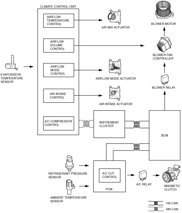
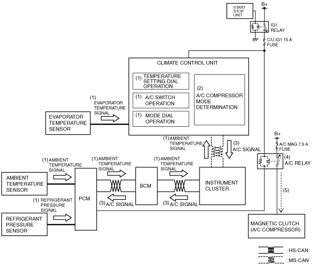
Block Diagram
amxuun00001285
|
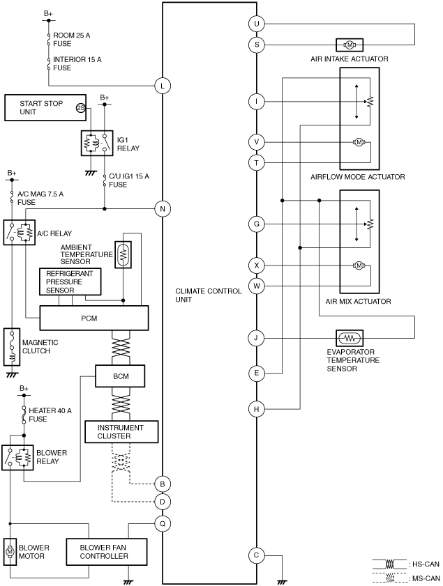
System Wiring Diagram
amxzzn00001221
|
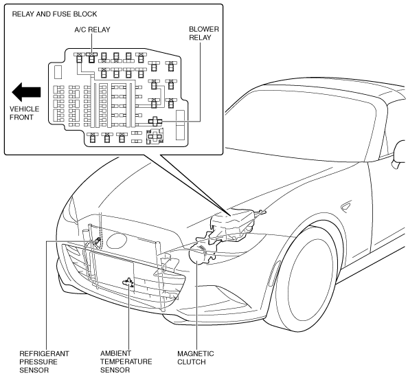
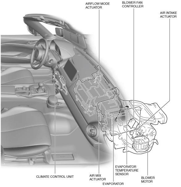
Structural View
amxuun00001287
|
amxzzn00000811
|
Operation
A/C compressor control
1. Based on the operation of each switch/dial and signals (1) from each sensor which change according to the vehicle conditions, the climate control unit performs A/C compressor mode determination (2) when the ignition is switched ON (engine off or on).
amxuun00001289
|
2. The climate control unit sends (3) the A/C signal to the PCM according to the result of the A/C compressor mode determination and corrections.
3. The PCM turns the A/C relay on (4) based on the A/C signal and the signals from each sensor which change according to the vehicle conditions.
4. When the A/C relay turns on, the magnetic clutch turns on (5).