 |
amxzzw00003106
AIR MIX ACTUATOR INSPECTION [MANUAL AIR CONDITIONER]
id0740a2802500
L.H.D.
1. Disconnect the negative battery cable. (See NEGATIVE BATTERY CABLE DISCONNECTION/CONNECTION.)
2. Remove the following parts:
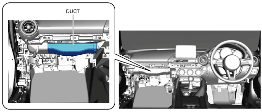
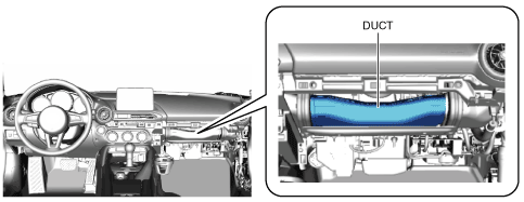
3. Remove the duct.
amxzzw00003106
|
4. Remove the air mix actuator. (See AIR MIX ACTUATOR REMOVAL/INSTALLATION [MANUAL AIR CONDITIONER].)
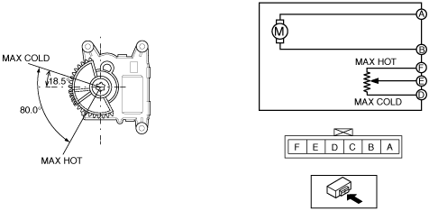
5. Apply battery positive voltage and connect the ground to the air mix actuator terminals as indicated in the table below and verify the operation condition.
|
B+ Terminal |
Ground Terminal |
Operation |
|---|---|---|
|
A
|
B
|
HOT → COLD
|
|
B
|
A
|
COLD → HOT
|
amxuuw00005674
|
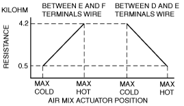
6. Verify that the resistance between terminals D and E, E and F matches the air mix actuator operation as shown in the graph.
amxuuw00005450
|
R.H.D.
1. Disconnect the negative battery cable. (See NEGATIVE BATTERY CABLE DISCONNECTION/CONNECTION.)
2. Remove the following parts:
3. Remove the duct.
amxzzw00003085
|
4. Remove the air mix actuator. (See AIR MIX ACTUATOR REMOVAL/INSTALLATION [MANUAL AIR CONDITIONER].)
5. Apply battery positive voltage and connect the ground to the air mix actuator terminals as indicated in the table below and verify the operation condition.
|
B+ Terminal |
Ground Terminal |
Operation |
|---|---|---|
|
A
|
B
|
COLD → HOT
|
|
B
|
A
|
HOT → COLD
|
amxzzw00003693
|
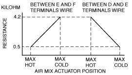
6. Verify that the resistance between terminals D and E, E and F matches the air mix actuator operation as shown in the graph.
amxzzw00003455
|