|
am2zzw00007803
POWER WINDOW MAIN SWITCH INSPECTION
id091200002100
1. Disconnect the negative battery cable. (See NEGATIVE BATTERY CABLE DISCONNECTION/CONNECTION.)
2. Remove the driver-side door trim. (See DOOR TRIM REMOVAL/INSTALLATION.)
3. Remove the power window main switch. (See POWER WINDOW MAIN SWITCH REMOVAL/INSTALLATION.)
4. Connect the power window main switch connector.
5. Connect the negative battery cable. (See NEGATIVE BATTERY CABLE DISCONNECTION/CONNECTION.)
6. Verify that the voltages of each of the terminals are as indicated in the terminal voltage table (reference).
Terminal Voltage Table (Reference)
am2zzw00007803
|
Power Window Main Switch
|
Terminal |
Signal name |
Connected to |
Measurement condition |
Voltage (V) |
Inspection item(s) |
|---|---|---|---|---|---|
|
1A
|
Ground
|
Body ground
|
Under any condition
|
1.0 or less
|
Body ground
|
|
1B
|
Power supply
|
P.WINDOW 30 A fuse
|
Under any condition
|
B+
|
• P.WINDOW 30 A fuse
• Battery
|
|
1C
|
Hall effect switch ground
|
Power window motor (driver's side)
|
Under any condition
|
1.0 or less
|
Power window motor (driver's side)
|
|
1D
|
Open signal
|
Power window motor (driver's side)
|
Door glass is performing open operation
|
B+
|
Power window motor (driver's side)
|
|
Door glass is performing open operation during approx. 40 s after ignition is switched from ON (engine off or on) to off
|
B+
|
||||
|
Other
|
1.0 or less
|
||||
|
1E
|
—
|
—
|
—
|
—
|
—
|
|
1F
|
Close signal
|
Power window motor (driver's side)
|
Door glass is performing close operation
|
B+
|
Power window motor (driver's side)
|
|
Door glass is performing close operation during approx. 40 s after ignition is switched from ON (engine off or on) to off
|
B+
|
||||
|
Other
|
1.0 or less
|
||||
|
1G
|
Hall effect switch power supply
|
Power window motor (driver's side)
|
Ignition is switched ON (engine off or on)
|
B+
|
Power window motor (driver's side)
|
|
Ignition is switched off (LOCK)
|
1.0 or less
|
||||
|
1H
|
Top lock switch signal*1
|
Top lock switch
|
Convertible top is close
|
B+
|
Top lock switch
|
|
Convertible top is open
|
1.0 or less
|
||||
|
Retractable hardtop control module signal*2
|
Retractable hardtop control module
|
Terminal used for communication therefore determination based on terminal voltage is not possible.
|
|||
|
1I
|
—
|
—
|
—
|
—
|
—
|
|
1J
|
Convertible top switch signal*1
|
Convertible top switch
|
Convertible top is close
|
B+
|
Convertible top switch
|
|
Convertible top is open
|
1.0 or less
|
||||
|
Retractable hardtop control module signal*2
|
Retractable hardtop control module
|
Terminal used for communication therefore determination based on terminal voltage is not possible.
|
|||
|
1K
|
IG1
|
C/U IG1 15 A fuse
|
Ignition is switched ON (engine off or on)
|
B+
|
• C/U IG1 15 A fuse
• Battery
|
|
1L
|
Serial communication
|
Power window subswitch
|
Terminal used for communication therefore determination based on terminal voltage is not possible.
|
||
|
2A
|
ACC
|
MIRROR 7.5 A fuse
|
Ignition is switched ON (engine off or on) or ACC
|
B+
|
• MIRROR 7.5 A fuse
• Battery
|
|
Ignition is switched off (LOCK)
|
1.0 or less
|
||||
|
2D
|
Hall effect switch No.1
|
Power window motor (driver's side)
|
Door glass (driver's side) is operating
|
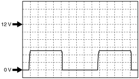
Wave pattern (See Inspection Using an Oscilloscope (Reference))
|
Power window motor (driver's side)
|
|
2F
|
Hall effect switch No.2
|
Power window motor (driver's side)
|
Door glass (driver's side) is performing open operation
|
Wave pattern (See Inspection Using an Oscilloscope (Reference))
|
Power window motor (driver's side)
|
|
2K
|
—
|
—
|
—
|
—
|
—
|
|
2L
|
Door switch signal
|
Door latch and lock actuator (driver's side)
|
Door is close
|
B+
|
Door latch and lock actuator (driver's side)
|
|
Door is open
|
1.0 or less
|
||||
|
2M
|
—
|
—
|
—
|
—
|
—
|
|
2N
|
—
|
—
|
—
|
—
|
—
|
Power Outer Mirror Switch
|
Terminal |
Signal name |
Connected to |
Measurement condition |
Voltage (V) |
Inspection item(s) |
|---|---|---|---|---|---|
|
2A
|
ACC
|
MIRROR 7.5 A fuse
|
Ignition is switched ON (engine off or on) or ACC
|
B+
|
• MIRROR 7.5 A fuse
• Battery
|
|
Ignition is switched off (LOCK)
|
1.0 or less
|
||||
|
2B
|
Power outer mirror right/down signal
|
Power outer mirror (LH)
|
Outer mirror glass (LH) is operating downward or to right direction
|
B+
|
Power outer mirror
|
|
Other
|
1.0 or less
|
||||
|
2C
|
Power outer mirror right/down signal
|
Power outer mirror (RH)
|
Outer mirror glass (RH) is operating downward or to right direction
|
B+
|
Power outer mirror
|
|
Other
|
1.0 or less
|
||||
|
2E
|
Ground
|
Body ground
|
Under any condition
|
1.0 or less
|
Body ground
|
|
2G
|
Power outer mirror left signal
|
Power outer mirror (LH)
|
Outer mirror glass (LH) is operating to left direction
|
B+
|
Power outer mirror
|
|
Other
|
1.0 or less
|
||||
|
2H
|
Power outer mirror up signal
|
Power outer mirror (LH/RH)
|
Outer mirror glass (LH/RH) is operating upward
|
B+
|
Power outer mirror
|
|
Other
|
1.0 or less
|
||||
|
2J
|
Power outer mirror left signal
|
Power outer mirror (RH)
|
Outer mirror glass (RH) is operating to left direction
|
B+
|
Power outer mirror
|
|
Other
|
1.0 or less
|
Inspection Using an Oscilloscope (Reference)
ac5jjw00003793
|