|
amxuun00000963
AUTO WIPER SYSTEM
id091900000900
Outline
Function
Personalization features
On-board diagnostic function
Structural View
amxuun00000963
|
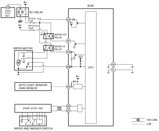
System Wiring Diagram
amxuun00000964
|
Operation
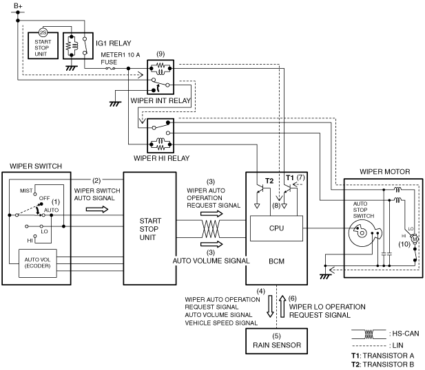
Intermittent operation/Continuous low speed operation
1. When the wiper switch is in the AUTO position (1) with the ignition switched ON (engine off or on), the start stop unit detects (2) the wiper switch AUTO signal.
2. When the start stop unit detects the wiper switch AUTO signal, the wiper AUTO operation request signal and the AUTO volume signal are sent (3) to the BCM by CAN communication.
3. The BCM sends (4) the wiper AUTO operation request signal and AUTO volume signal, and the vehicle speed signal sent from the PCM to the rain sensor by LIN communication.
4. When the rain sensor receives the wiper AUTO operation request signal, it detects (5) the amount of rainfall.
5. The rain sensor determines the operation interval of the wipers based on the detected rainfall amount and illumination level, and sends (6) a wiper LO operation request signal to the BCM.
6. When the BCM receives the wiper LO operation request signal, it turns transistor A on (7).
7. When transistor A turns on, a ground circuit with the wiper INT relay is established (8), and the wiper INT relay turns on (9).
8. When the wiper INT relay turns on, the wipers operate intermittently or at low continuous operation (10).
amxuun00000965
|
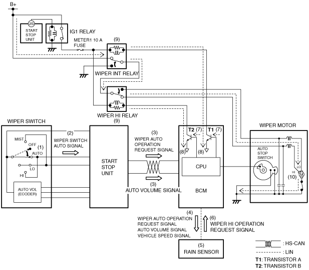
High speed operation
1. When the wiper switch is in the AUTO position (1) with the ignition switched ON (engine off or on), the start stop unit detects (2) wiper switch AUTO signal.
2. When the start stop unit detects the wiper switch AUTO signal, the wiper AUTO operation request signal and the AUTO volume signal are sent (3) to the BCM by CAN communication.
3. The BCM sends (4) the wiper AUTO operation request signal and AUTO volume signal, and the vehicle speed signal sent from the PCM to the rain sensor by LIN communication.
4. When the rain sensor receives the wiper AUTO operation request signal, it detects (5) the amount of rainfall.
5. The rain sensor determines the operation interval of the wipers based on the detected rainfall amount and illumination level, and sends (6) a wiper HI operation request signal to the BCM.
6. When the BCM receives the wiper HI operation request signal, it turns transistors A and B on (7).
7. When transistors A and B turn on, a ground circuit with the wiper INT relay and the wiper HI relay are established (8), and the wiper INT relay and wiper HI relay turn on (9).
8. When the wiper INT relay and wiper HI relay turn on, the wipers operate at high speed (10).
amxuun00000966
|