BODY CONTROL MODULE (BCM)
id094000004100
Purpose
• The BCM performs control of multiple systems such as the power door locks and the windshield wipers and washer based on the input signals such as from the light switch, door key cylinder switch, and the wiper and washer switch.
Function
• The BCM control content is as follows.
Control table
|
Control
|
Content
|
Reference
|
|
Turn light system
|
The BCM performs control of the turn light system based on the signal from the turn switch.
|
|
|
Map light
|
The BCM performs control of the map light based on the signals from the door latch switch and interior light switch.
|
|
|
Coming home light system
|
The BCM performs control of the coming home light system based on the signals from the light switch and the door light switch.
|
|
|
Leaving home light system
|
The BCM performs control of the leaving home light system based on the signals from the light switch and the remote transmitter.
|
|
|
Power door lock system
|
The BCM performs control of the power door lock system based on the signal from the door look link switch or door key cylinder switch.
|
|
|
Trunk lid opener system
|
The BCM performs control of the trunk lid opener system based on the signal from the trunk lid opener switch.
|
|
|
Windshield wiper
|
The BCM performs control of the windshield wipers based on the signal from the wiper and washer switch.
|
|
|
Blower system
|
The BCM performs control of the blower relay based on the request signal from the PCM.
|
|
|
Rear window defogger
|
The BCM performs control of the rear window defogger relay based on the signal from the climate control unit.
|
|
|
Horn
|
The BCM performs control of the horn relay based on the signal from the horn system.
|
|
|
Headlight cleaner
|
The BCM controls the headlight cleaner based on the signal from the wiper and washer switch.
|
|
|
Theft-deterrent system
|
The BCM controls the theft-deterrent system based on the signals from the door latch switch, trunk lid latch switch, hood latch switch, and door lock link switch.
|
|
Battery Discharge Suppression Function
-
• When the PCM is performing i-ELOOP control and i-stop control, the PCM stops the following functions based on the request signal from the PCM to prevent a vehicle malfunction due to a decrease in power supply voltage.
-
― Rear window defogger
― Blower motor
Dark current reduction function
-
• When the ignition is switched off or in the ACC position and all of the following conditions are met, the BCM cuts off the power supply input circuit of the CAN communication and BCM to reduce dark current.
-
― 20 s or more have elapsed since ignition was switched off or in ACC position
― Turn light output control is off
― Horn output control is off
― ISO communication between the start stop unit and BCM not performed
― Security indicator light is not turned on/flashing
― LIN communication between the electrical supply unit (ESU) and the BCM is not performed
Automatic configuration function
-
• When the ignition is switched ON after the BCM is replaced, the BCM reads the vehicle specification information sent via CAN signal from the instrument cluster, and stores the vehicle specification information.
-
Note
-
• The personalization setting content stored by the BCM cannot be read by auto configuration. If the personalization setting content is to be read from the pre-replacement BCM to the post-replacement BCM, implement the BCM configuration (use read/write function). For the BCM configuration (using the read/write function) procedure, refer to the [BODY CONTROL MODULE (BCM) CONFIGURATION (USING READ/WRITE FUNCTION)] in the workshop manual.
Construction
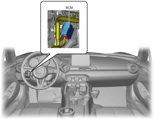
L.H.D.
• The BCM is located inside the lower panel on the driver seat side.
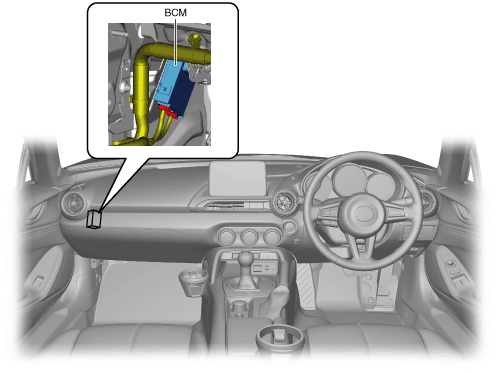
R.H.D.
• The BCM is located inside the lower panel on the passenger seat side.
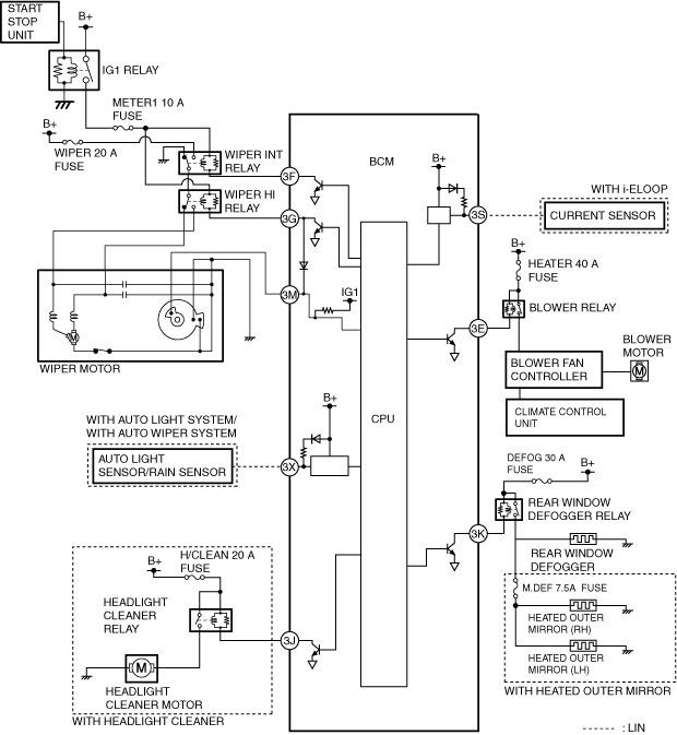
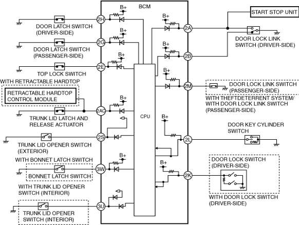
System Wiring Diagram
Windshield wiper, rear window defogger, blower motor, current sensor, headlight cleaner
Door lock, trunk lid opener
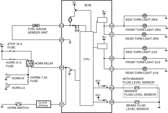
Fuel gauge sender unit, horn, brake fluid level sensor, washer fluid-level sensor, turn light
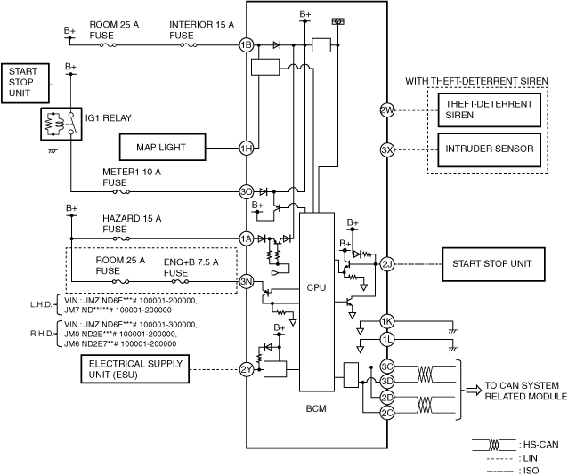
Power supply, LIN communication, ISO communication, CAN system, theft-deterrent system
Operation
For the operation of each control, refer to the following system operations.
-
-
-
-
-
-
-
-
-
-
• Horn control (See
HORN.)
-
-
Fail-safe
Exterior lighting system
-
• If any of the following malfunctions occurs, the BCM turns the TNS and headlights LO on, and stops other exterior light control.
-
― Malfunction in CPU in BCM detected
― CAN communication error (cannot receive light switch position signal)
Auto-light system
-
• If any of the following malfunctions occurs, the BCM operates using the controls prior to the auto-light malfunction detection.
-
― Malfunction in CPU in BCM detected
― CAN communication error (cannot receive wiper switch position signal)
― LIN communication error (cannot receive signal from auto-light sensor)
Running light system (With Running light system)
-
• If the BCM detects a vehicle speed signal error, it controls the running light system as a 3 km/h {2 mph} or more vehicle speed condition.
Interior light control system
-
• If the following malfunction occurs, the BCM performs control for a continuous 5 s period using controls prior to the interior light malfunction detection, and after 5 s have elapsed, it turns on using the initial value.
-
― CAN communication error (cannot receive ignition switch condition signal)
Power door lock system
-
• Not applicable
Trunk lid opener system
-
• Not applicable
Windshield wiper system
-
• If any of the following malfunctions occurs, the BCM operates using the controls prior to the windshield wiper malfunction detection.
-
― Malfunction in CPU in BCM detected
― CAN communication error (cannot receive wiper switch position signal)
-
• If an auto stop switch malfunction (wiper operation status unknown) during the wiper operation is detected, the BCM stops the wiper operation.
Washer system
-
• If any one of the following malfunctions occurs, the BCM stops control of the washer.
-
― Malfunction in CPU in BCM detected
― CAN communication error (cannot receive wiper switch position signal)
Auto wiper system
-
• If any of the following malfunctions occurs, the BCM operates using the controls prior to the auto-wiper malfunction detection.
-
― Malfunction in CPU in BCM detected
― CAN communication error (cannot receive wiper switch position signal)
― LIN communication error (cannot receive signal from lane sensor)
Blower system
-
• If the ignition switch condition signal cannot be received or a malfunction signal is received which was sent via CAN communication from the instrument cluster, the following controls are performed.
-
― BCM power supply condition is on: Blower relay is turned on
― BCM power supply condition is off: Blower relay is turned off
Rear window defogger
-
• Not applicable
Horn
-
• The BCM turns off the horn relay when a CAN communication error is detected.