i-ELOOP [i-ELOOP]
id131704500000
Outline
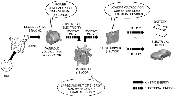
• i-ELOOP is a regenerative braking system which consists mainly of three parts, a variable voltage type generator, a capacitor (i-ELOOP), and a DC-DC converter (i-ELOOP).
Kinetic energy occurring when the vehicle decelerates in the fuel cut range during deceleration is converted to electrical energy by the generator and stored in the capacitor (i-ELOOP). The stored electricity is used as power for the vehicle’s electrical devices (such as A/C, audio unit), and reduced fuel consumption can be expected by the minimized loss of engine output (generator operation loss).
• A variable voltage type generator has been adopted which can generate 12—24.3 V according to the vehicle and capacitor (i-ELOOP) conditions. Using the characteristic of electricity in which current flows to the low electrical potential from the high electrical potential, electricity can be stored in the capacitor (i-ELOOP) by generating higher voltage than the capacitor (i-ELOOP) voltage.
• A capacitor (i-ELOOP) has been adopted as a condenser which can instantaneously store large amounts of electricity generated by the generator. A characteristic of the capacitor (i-ELOOP) is its ability to supply electricity quickly when it is used. The capacitor (i-ELOOP) stores the voltage generated by the variable voltage type generator (maximum of 24.3 V).
• A DC-DC converter (i-ELOOP) has been adopted which supplies electricity to the vehicle’s electrical devices by lowering the voltage (maximum of 24.3 V) stored in the capacitor (i-ELOOP).
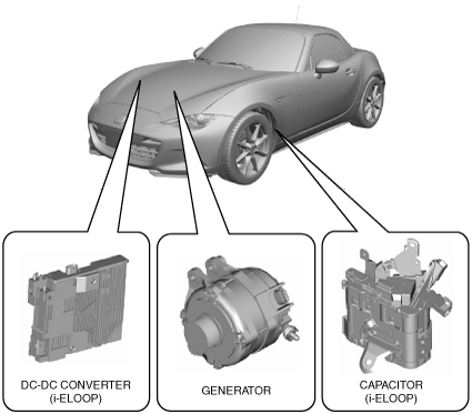
Structural View
• i-ELOOP consists mainly of the following parts.
|
Part name
|
Reference
|
|
Capacitor (i-ELOOP)
|
|
|
DC-DC converter (i-ELOOP)
|
|
|
Generator
|
|
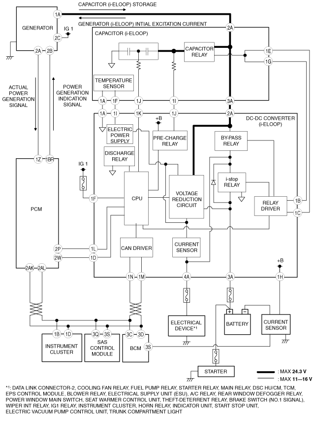
System Wiring Diagram
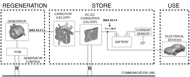
Operation
• The operation aspect of i-ELOOP is as follows.
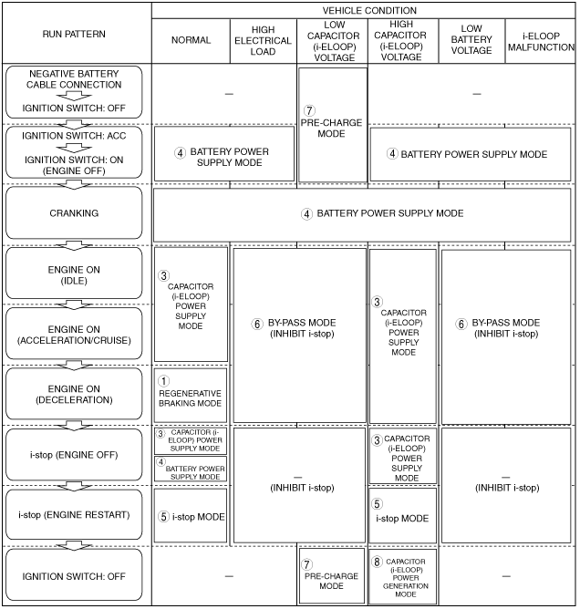
• The i-ELOOP operation mode varies depending on the vehicle driving conditions and the conditions of i-ELOOP-related parts.
|
Condition
|
Operation mode
|
Reference
|
|
Regeneration, store, storage
|
1.Regenerative braking mode
|
|
|
2. Conventional power generation mode (no regenerative braking)
|
|
|
Use
|
3. Capacitor (i-ELOOP) power supply mode
|
|
|
4. Battery power supply mode
|
|
|
5. i-stop mode
|
|
|
6. By-pass mode
|
|
|
Other mode
|
7. Pre-charge mode
|
|
|
8. Capacitor (i-ELOOP) power generation mode
|
|
1. Regenerative braking mode
-
Purpose
-
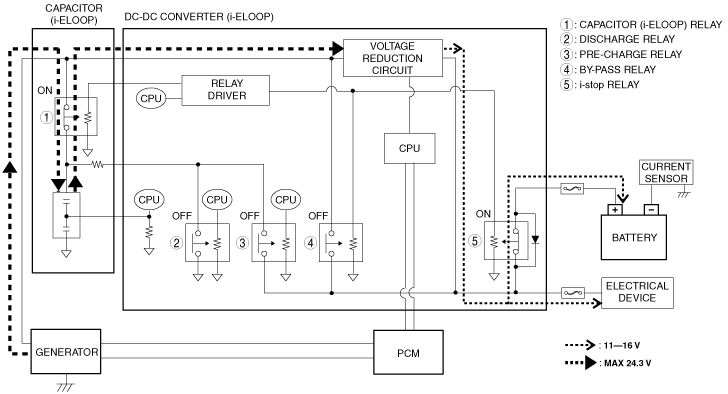
• The regenerative braking mode generates electricity at the generator in the fuel cut (deceleration regeneration) range during deceleration and stores electricity in the capacitor (i-ELOOP).
The PCM determines the generator power generation amount according to the capacitor (i-ELOOP) voltage and stores the electricity in the capacitor (i-ELOOP). When the capacitor (i-ELOOP) voltage reaches 24.3 V during deceleration regeneration, the PCM determines that the capacitor (i-ELOOP) is fully charged and limits the generator output.
• Although the regenerative braking mode is mainly for the purpose of storing electricity in the capacitor (i-ELOOP), the electricity generated by the generator is supplied to the vehicle’s electrical devices and battery via the voltage reduction circuit in the DC-DC converter (i-ELOOP).
-
Note
-
• The electricity output from the voltage reduction circuit is supplied to the vehicle's electrical devices and battery because the voltage after the voltage reduction circuit in the DC-DC converter (i-ELOOP) is higher than the voltage applied to the battery voltage and vehicle's electrical devices.
-
Operation condition
-
• During fuel-cut by release of accelerator pedal and TCC
2. Conventional power generation mode (no regenerative braking)
-
Purpose
-
• If the capacitor (i-ELOOP) voltage is the specified value or less while the engine is running, electricity generated by the conventional power generation mode (non-regenerative braking) is supplied to the vehicle’s electrical devices.
Because the capacitor (i-ELOOP) at this time lacks sufficient electricity to supply power to the vehicle’s electrical devices, fuel is consumed and electricity is generated by the generator for the purpose of assuring a power supply to the vehicle’s electrical devices.
• Although the generator generates constant voltage the same as that of the previous-type power generation mode, it can actually generate between 12 and 24.3 V. The generator remains on stand-by so that reduction regeneration is performed as soon as the operation condition of the regenerative braking mode is met.
-
Note
-
• Although the relay operation condition in the DC-DC converter (i-ELOOP) is the same as the regenerative braking mode, engine drive force is used for generating electricity in this mode.
• The conventional power generation mode cannot store electricity sufficiently in the capacitor (i-ELOOP) because the generated power amount is lower compared to the regenerative braking mode.
-
Operation condition
-
• capacitor (i-ELOOP) voltage is specified value or less with engine running
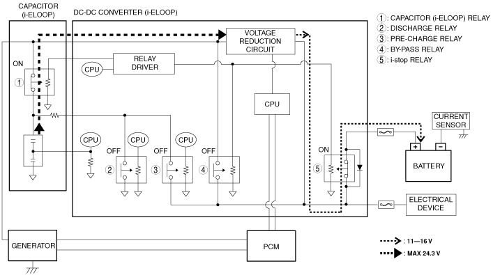
3. Capacitor (i-ELOOP) power supply mode
-
Purpose
-
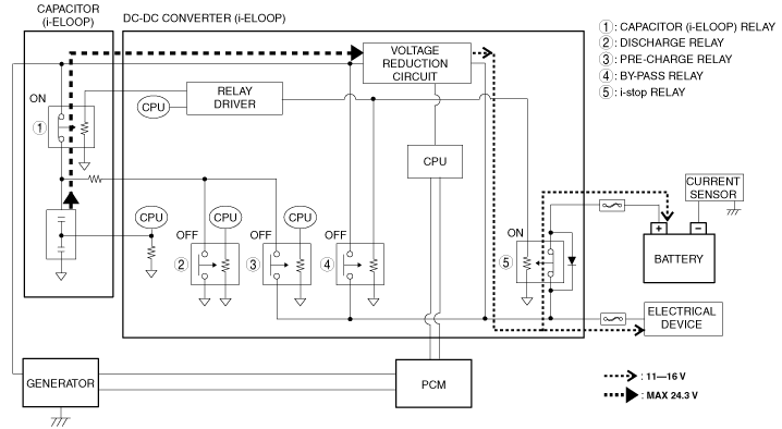
• If the capacitor (i-ELOOP) voltage is higher than the battery voltage, the capacitor (i-ELOOP) power supply mode lowers the voltage stored by the capacitor (i-ELOOP) using the DC-DC converter (i-ELOOP) to supply power to the vehicle’s electrical devices.
• The generator does not generate electricity while in the capacitor (i-ELOOP) power supply mode and power is supplied to the vehicle’s electrical devices using the capacitor (i-ELOOP) electricity regardless of the driving conditions (such as during acceleration) as long as the capacitor (i-ELOOP) voltage is higher than the battery voltage.
-
Note
-
• The capacitor (i-ELOOP) voltage lowers gradually because the electricity stored in the capacitor (i-ELOOP) is used while in the capacitor (i-ELOOP) power supply mode. If the capacitor (i-ELOOP) voltage is the specified value or less, the DC-DC converter (i-ELOOP) stops the operation of the capacitor (i-ELOOP) power supply mode.
-
Operation condition
-
• Capacitor (i-ELOOP) voltage is specified value or more
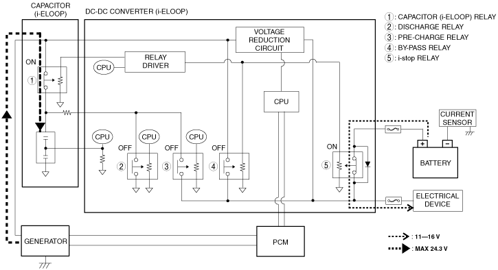
4. Battery power supply mode
-
Purpose
-
• The battery power supply mode supplies power to the vehicle’s electrical devices from the battery.
• The same as in conventional vehicles, battery electricity is supplied to the vehicle’s electrical devices and the starter during cranking (except when engine is restarted by i-stop). Battery electricity is supplied to the vehicle’s electrical devices in the same way whether the ignition is switched to ACC or ON (engine off).
• The battery power supply mode operates even while the engine is stopped by i-stop control.The electricity stored in the capacitor (i-ELOOP) is supplied to the vehicle’s electrical devices while the engine is stopped by i-stop control (capacitor (i-ELOOP) power supply mode). After that, if the capacitor (i-ELOOP) voltage is the specified value or less, battery electricity is supplied to the vehicle’s electrical devices to stop the capacitor (i-ELOOP) power supply mode and continue to stop the engine by i-stop control.
-
Operation condition
-
• Under any of the following conditions:
-
― During engine cranking
― Ignition is switched to ACC or ON (engine off)
― When capacitor (i-ELOOP) voltage is specified value or less while engine is stopped by i-stop control
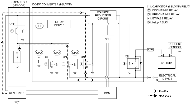
5. i-stop mode (Engine restart)
-
Purpose
-
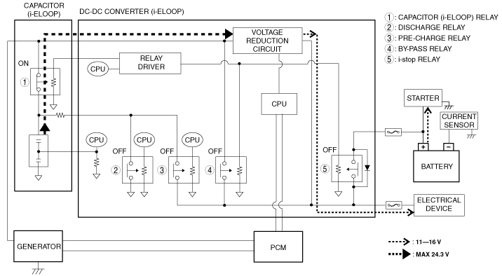
• To supply power to the vehicle’s electrical devices (such as instrument cluster or headlights) assuredly when the engine is restarted by i-stop, the i-stop mode divides the source of the power supply between the battery and capacitor (i-ELOOP).
-
Note
-
• The vehicle’s electrical devices are supplied power from the voltage reduction circuit and the starter is supplied power from the battery by turning the i-stop relay in the DC-DC converter (i-ELOOP) off.
-
Operation condition
-
• The electricity from the battery is not supplied to the vehicle’s electrical devices via the diode in the i-stop relay because the voltage output from the voltage reduction circuit in the DC-DC converter (i-ELOOP) is higher than the battery voltage.
6. By-pass mode
-
Purpose
-
• When the power consumption of the vehicle’s electrical devices exceeds the output limit of the voltage reduction circuit in the DC-DC converter (i-ELOOP), or the capacitor (i-ELOOP) voltage is low, the bypass mode turns the bypass relay on and supplies electricity generated by the generator directly to the vehicle’s electrical devices via the bypass relay.
-
Caution
-
• i-stop control is inhibited in the bypass mode because the vehicle’s electric load is high.
-
Note
-
• Because the electricity generated by the generator is supplied directly to the vehicle’s electrical devices and battery without passing through the voltage reduction circuit in the bypass mode, the voltage generated by the generator is controlled by the PCM at the rated voltage of the vehicle’s electrical devices.
-
Operation condition
-
• When any one of the following conditions is met:
-
― Vehicle electric load is high (current consumption is 75 A or more)
― Any one of i-ELOOP parts (capacitor (i-ELOOP)/DC-DC converter (i-ELOOP)) is malfunctioning
― Capacitor (i-ELOOP) voltage when ignition is switched ON (engine off): less than 7.5 V
― Battery charge condition: Less than 65%
― Voltage reduction circuit temperature: 131 °C {268 °F} or more
― Bypass relay temperature: 125 °C {257 °F} or more
-
*1: If the vehicle electric load is high (current consumption is 75 A or more), the electricity generated by the generator is supplied to the capacitor (i-ELOOP) with the capacitor (i-ELOOP) relay ON.
7. Pre-charge mode
-
Purpose
-
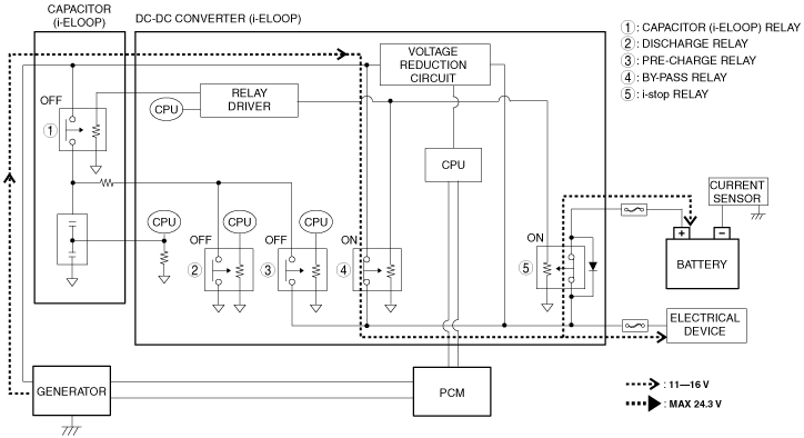
• When the capacitor (i-ELOOP) self-discharges (vehicle left for long periods without starting engine) or the capacitor (i-ELOOP) voltage from the back-up current is the specified value or less, the pre-charge mode charges electricity to the capacitor (i-ELOOP) by supplying power to the capacitor (i-ELOOP) from the battery or generator.
• The power supply method differs depending on the vehicle conditions while in the pre-charge mode as follows.
Pre-charge operation
|
Cause
|
Step
|
Operation condition/power supply method
|
i-ELOOP indicator light (green)
|
Following figure
|
|
• Replacement of capacitor (i-ELOOP) only
• Capacitor (i-ELOOP) self-discharge (vehicle left unattended for long periods) or decrease in capacitor (i-ELOOP) voltage due to back-up current consumption
|
1. Negative battery cable is connected
|
Operation condition
• Capacitor (i-ELOOP) voltage is less than 7.5 V
Power supply method
• The capacitor (i-ELOOP) relay is turned off and the pre-charge relay is turned on, and power is supplied from the battery to the capacitor (i-ELOOP) (to capacitor (i-ELOOP) voltage of 9.5 V or more) via the pre-charge relay.
|
NOT DISPLAYED
|
A
|
|
2. Ignition switched ON (engine off to on)
|
Operation condition
• Capacitor (i-ELOOP) voltage is less than 7.5 V
Power supply method
1. The capacitor (i-ELOOP) relay is turned off, the bypass relay is turned on, and the pre-charge relay is turned on, and power is supplied from the generator to the capacitor (i-ELOOP) via the pre-charge relay through the bypass relay. At this time, it remains fixed in bypass mode until the ignition is switched OFF.
2. The pre-charge ends at the point where the capacitor (i-ELOOP) voltage is 9.5 V or more.
|
B
|
|
Capacitor (i-ELOOP) voltage is low (ex. capacitor (i-ELOOP) replacement) during replacement of DC-DC converter (i-ELOOP)
|
1. Negative battery cable is connected
|
Operation condition
• When all of the following conditions are met:
-
― DC-DC converter (i-ELOOP) is first assembled
― Capacitor (i-ELOOP) voltage is less than 3.5 V
Power supply method
• The capacitor (i-ELOOP) relay is turned off and the pre-charge relay is turned on, and power is supplied from the battery to the capacitor (i-ELOOP) (to capacitor (i-ELOOP) voltage of 3.5 V or more) via the pre-charge relay.
|
NOT DISPLAYED
|
A
|
|
2. Ignition switched ON (engine off to on)
|
Operation condition
• When all of the following conditions are met:
-
― DC-DC converter (i-ELOOP) is first assembled
― Capacitor (i-ELOOP) voltage is less than 7.5 V
Power supply method
1. The capacitor (i-ELOOP) relay is turned on and the pre-charge relay is turned off, and power is supplied from the generator to the capacitor (i-ELOOP).
2. The pre-charge ends at the point where the capacitor (i-ELOOP) voltage is 9.5 V or more.
|
Flash*1/no display
|
C
|
|
• If the ignition is switched OFF during pre-charge mode and the capacitor (i-ELOOP) charge is insufficient, the pre-charge mode continues.
Operation condition
• Hood is closed and capacitor (i-ELOOP) voltage is less than 9.5 V
Power supply method
• The capacitor (i-ELOOP) relay is turned off and the pre-charge relay is turned on, and power is supplied from the battery to the capacitor (i-ELOOP) (to capacitor (i-ELOOP) voltage of 9.5 V or more) via the pre-charge relay.
|
A
|
*1 :If the capacitor (i-ELOOP) voltage is low (such as capacitor (i-ELOOP) replacement) when the DC-DC converter (i-ELOOP) is replaced, the DC-DC converter (i-ELOOP) sends an i-ELOOP indicator light (green) flash request to the instrument cluster.
-
Note
-
• If the capacitor (i-ELOOP) voltage decreases to the specified value or less due to the capacitor (i-ELOOP) not being used for long periods, the excitation current of the generator drawn from the initial excitation current from the capacitor (i-ELOOP) is low. Therefore, the generator cannot generate power even if the engine is started. In addition, power may not be supplied from the capacitor (i-ELOOP) to the battery and the vehicle’s electrical devices because the electrical potential of the capacitor (i-ELOOP) is lower than the battery.
To assure excitation current to the generator and capacitor (i-ELOOP) voltage, the capacitor (i-ELOOP) is disconnected using the capacitor (i-ELOOP) relay and switched to bypass mode. As a result, power is supplied from the battery and generator and electricity is stored in the capacitor (i-ELOOP) while assuring power to the vehicle.
A: Power is supplied from battery to capacitor (i-ELOOP) (via pre-charge relay)
B: Power is supplied from generator to capacitor (i-ELOOP) (via pre-charge relay through bypass relay)
C: Power is supplied from generator to capacitor (i-ELOOP) (via capacitor (i-ELOOP) relay)
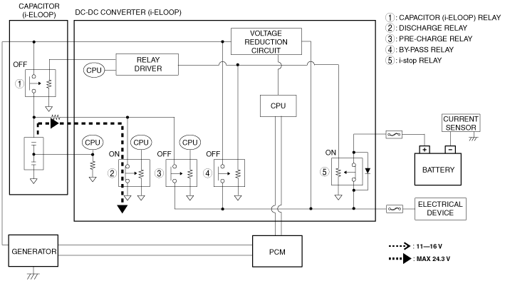
8. Capacitor (i-ELOOP) power generation mode
-
Purpose
-
• When the capacitor (i-ELOOP) voltage is the specified value or more with the ignition switched OFF, the capacitor (i-ELOOP) discharging mode charges the battery using the surplus power stored in the capacitor (i-ELOOP).
The electricity stored in the capacitor (i-ELOOP) is lowered by the DC-DC converter (i-ELOOP) and power is supplied to the battery.
• If the battery voltage is high and power cannot be supplied from the capacitor (i-ELOOP) to the battery, the discharge relay is turned on and the capacitor (i-ELOOP) voltage is discharged until it is the specified value or less.
-
Note
-
• If a condition continues for a long period in which the capacitor (i-ELOOP) is close to being fully charged, the capacitor (i-ELOOP) performance (such as internal resistance, capacitance) may decrease. Therefore, when the ignition is switched OFF, the capacitor (i-ELOOP) performance is maintained by charging the battery using the surplus power in the capacitor (i-ELOOP) and discharging the capacitor (i-ELOOP) electricity.
• To assure safety for servicing, if the DC-DC converter (i-ELOOP) detects that the hood is open, it stops supplying power from the capacitor (i-ELOOP) to the battery, turns the discharge relay on, and discharges the capacitor (i-ELOOP) voltage until it is the specified value or less.
-
Operation condition
-
• When any one of the following conditions is met:
-
― Capacitor (i-ELOOP) voltage is the specified value or more with ignition switched OFF
― Hood is open
When power is supplied to battery
When power cannot be supplied to battery
• The following are examples of the i-ELOOP operation in each mode.
• The following are the relay conditions for each operation mode.
×: Relay ON
—: Relay OFF
|
Operation mode
|
capacitor (i-ELOOP) relay
|
Discharge relay
|
Pre-charge relay
|
By-pass relay
|
i-stop relay
|
|
1.Regenerative braking mode
|
×
|
—
|
—
|
—
|
×
|
|
2. Conventional power generation mode (no regenerative braking)
|
×
|
—
|
—
|
—
|
×
|
|
3. Capacitor (i-ELOOP) power supply mode
|
×
|
—
|
—
|
—
|
×
|
|
4. Battery power supply mode
|
×
|
—
|
—
|
—
|
×
|
|
5. i-stop mode
|
×
|
—
|
—
|
—
|
—
|
|
6. By-pass mode
|
×*1/×*2
|
—
|
—
|
|
×
|
|
7. Pre-charge mode
|
Negative battery cable is connected
|
—
|
—
|
×
|
—
|
×
|
|
Pre-charge after ignition switched OFF
|
|
Ignition switched ON
(Replacement of capacitor (i-ELOOP) only/capacitor (i-ELOOP) self-discharge (vehicle left unattended for long periods) or decrease in capacitor (i-ELOOP) voltage due to back-up current consumption)
|
—
|
—
|
×
|
×
|
×
|
|
Ignition switched ON
(Capacitor (i-ELOOP) voltage is low (ex. capacitor (i-ELOOP) replacement) during replacement of DC-DC converter (i-ELOOP))
|
×
|
—
|
—
|
—
|
×
|
|
8. Capacitor (i-ELOOP) power generation mode
|
When power is supplied to battery
|
×
|
—
|
—
|
—
|
×
|
|
When power cannot be supplied to battery or hood is opened
|
—
|
×
|
—
|
—
|
×
|
*1 :If vehicle electrical load is high or when voltage reduction circuit is overheated
*2 :At the time except for *1
i-ELOOP status verification
-