BLIND SPOT MONITORING (BSM) SWITCH INSPECTION


id152000004000

Note
•  The blind spot monitoring (BSM) switch is integrated with the cluster switch.
•  To replace the blind spot monitoring (BSM) switch, replace the cluster switch. (See CLUSTER SWITCH REMOVAL/INSTALLATION.)

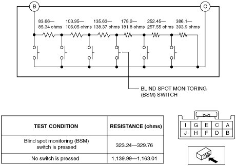
Resistance Inspection

1.  Disconnect the negative battery cable. (See NEGATIVE BATTERY CABLE DISCONNECTION/CONNECTION.)

2.  Remove the following parts:

(1)  Driver-side scuff plate (See SCUFF PLATE REMOVAL/INSTALLATION.)
(2)  Driver-side front side trim (See FRONT SIDE TRIM REMOVAL/INSTALLATION.)
(3)  Driver-side A-pillar trim (See A-PILLAR TRIM REMOVAL/INSTALLATION.)
(4)  Cluster switch (See CLUSTER SWITCH REMOVAL/INSTALLATION.)

3.  Verify that the resistance between cluster switch terminals B and C is as indicated in the table.

am2zzw00011537

•  If not within the specification, replace the cluster switch. (See CLUSTER SWITCH REMOVAL/INSTALLATION.)


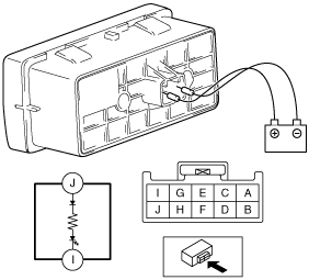
LED Illumination Inspection

1.  Disconnect the negative battery cable. (See NEGATIVE BATTERY CABLE DISCONNECTION/CONNECTION.)

2.  Remove the following parts:

(1)  Driver-side scuff plate (See SCUFF PLATE REMOVAL/INSTALLATION.)
(2)  Driver-side front side trim (See FRONT SIDE TRIM REMOVAL/INSTALLATION.)
(3)  Driver-side A-pillar trim (See A-PILLAR TRIM REMOVAL/INSTALLATION.)
(4)  Cluster switch (See CLUSTER SWITCH REMOVAL/INSTALLATION.)

3.  Apply battery positive voltage to cluster switch terminal J, and connect terminal I to ground.

adejjw00011278

4.  Verify that the LED is turned on.

•  If the LED does not turn on, replace the cluster switch. (See CLUSTER SWITCH REMOVAL/INSTALLATION.)