|
ghg0517m5004
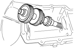
MAINSHAFT COMPONENT, COUNTERSHAFT COMPONENT AND TRANSMISSION CASE ASSEMBLY
d5e051117040m02
1. Assemble in the order indicated in the table.
ghg0517m5004
|
|
1
|
Transmission case
|
|
2
|
Countershaft component
|
|
3
|
Mainshaft component
|
|
4
|
Maindrive gear
|
|
5
|
Countershaft front bearing
|
|
6
|
Countershaft rear bearing
|
|
7
|
Maindrive gear bearing race
|
|
8
|
Mainshaft bearing race
|
|
9
|
Bearing cover
|
|
10
|
Front oil seal
(See Front Oil Seal Assembly Note.)
|
|
11
|
Bearing shim
|
|
12
|
Bearing shim
|
|
13
|
Oil baffle
|
|
14
|
Front cover
|
|
15
|
Front cover No.2
|
Front Oil Seal Assembly Note
1. Install the oil seal to the front cover using the SST.
e5u511bm5043
|
Maindrive Gear Component, Mainshaft Component and Countershaft Component Assembly Note
1. Install the countershaft component.
e5u511bm5073
|
2. Install the mainshaft component.
e5u511bm5044
|
3. Insert the maindrive gear component from the front cover hole and assemble to the mainshaft component.
e5u511bm5045
|
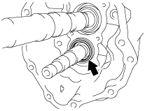
4. Install the countershaft front and center bearing.
e5u511bm5046
|
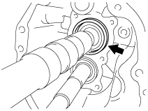
5. Install the maindrive gear bearing race and mainshaft center bearing race.
e5u511bm5047
|
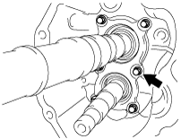
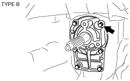
6. Install the bearing cover with the arrow pointing to the top of the case.
e5u511bm5048
|
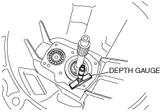
7. Select the mainshaft component and countershaft component bearing shims according to the following procedure.
e5u511bm5049
|
e5u511bm5050
|
Maindrive gear bearing shim selective chart
|
Dimension C (mm {in}) |
Shim thickness (mm {in}) |
|---|---|
|
2.75—2.85
{0.1083—0.1122}
|
2.7 {0.106}
|
|
2.85—2.95
{0.1122—0.1161}
|
2.8 {0.110}
|
|
2.95—3.05
{0.1161—0.1201}
|
2.9 {0.114}
|
|
3.05—3.15
{0.1201—0.1240}
|
3.0 {0.118}
|
|
3.15—3.25
{0.1240—0.1280}
|
3.1 {0.122}
|
|
3.25—3.35
{0.1280—0.1319}
|
3.2 {0.126}
|
|
3.35—3.45
{0.1319—0.1358}
|
3.3 {0.130}
|
|
3.45—3.55
{0.1358—0.1398}
|
3.4 {0.134}
|
|
3.55—3.65
{0.1398—0.1437}
|
3.5 {0.138}
|
|
3.65—3.75
{0.1437—0.1476}
|
3.6 {0.142}
|
|
3.75—3.85
{0.1476—0.1516}
|
3.7 {0.147}
|
|
3.85—3.95
{0.1516—0.1555}
|
3.8 {0.150}
|
|
3.95—4.05
{0.1555—0.1594}
|
3.9 {0.154}
|
|
4.05—4.15
{0.1594—0.1634}
|
4.0 {0.157}
|
|
4.15—4.25
{0.1634—0.1673}
|
4.1 {0.161}
|
e5u511bm5052
|
e5u511bm5053
|
Countershaft front bearing shim selective chart
|
Dimension F (mm {in}) |
Shim thickness (mm {in}) |
|---|---|
|
2.45—2.55
{0.0965—0.1004}
|
2.3 {0.091}
|
|
2.55—2.65
{0.1004—0.1043}
|
2.4 {0.094}
|
|
2.65—2.75
{0.1043—0.1083}
|
2.5 {0.098}
|
|
2.75—2.85
{0.1083—0.1122}
|
2.6 {0.102}
|
|
2.85—2.95
{0.1122—0.1161}
|
2.7 {0.106}
|
|
2.95—3.05
{0.1161—0.1201}
|
2.8 {0.110}
|
|
3.05—3.15
{0.1201—0.1240}
|
2.9 {0.114}
|
|
3.15—3.25
{0.1240—0.1280}
|
3.0 {0.118}
|
|
3.25—3.35
{0.1280—0.1319}
|
3.1 {0.122}
|
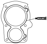
8. Position the maindrive gear bearing shim, oil baffle, and the countershaft bearing shim onto the front cover.
9. Apply sealant to the contact surfaces of the transmission case and front cover as shown in the figure.
e5u511bm5078
|
10. Install the front cover to the transmission case.
ghg0517m5005
|
ghg0517m5006
|