|
amxzzw00001234
WHEEL HUB, STEERING KNUCKLE REMOVAL/INSTALLATION
id031100800400
1. Remove in the order indicated in the table.
2. Install in the reverse order of removal.
3. After installation, inspect front wheel alignment. (See FRONT WHEEL ALIGNMENT.)
amxzzw00001234
|
|
1
|
ABS wheel-speed sensor
|
|
2
|
Brake calliper component
|
|
3
|
Disc plate
|
|
4
|
Tie-rod end
|
|
5
|
Stabilizer control link nut (lower)
|
|
6
|
Front upper arm ball joint
|
|
7
|
Front upper arm bolt
|
|
8
|
Front lower arm ball joint
|
|
9
|
Steering knuckle component
|
|
10
|
Steering knuckle
|
|
11
|
Dust cover
|
|
12
|
Wheel hub bolt
(See Wheel Hub Bolt Removal Note.)
|
|
13
|
Wheel hub component
|
Brake Caliper Component Removal Note
1. Suspend the brake calliper component using a cable or equivalent.
amxzzw00001235
|
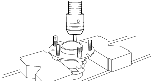
Wheel Hub Bolt Removal Note
1. Remove the wheel hub bolts from the wheel hub using a press.
amxzzw00001236
|
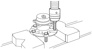
Wheel Hub Bolt Installation Note
1. Press in new wheel hub bolts into the wheel hub using a press.
amxzzw00001237
|