DTC C1095, C1096 [DYNAMIC STABILITY CONTROL (DSC)]


id0402b2805900

DTC
C1095, C1096
Pump motor, motor relay system
DETECTION CONDITION
•  C1095
―  When the motor relay is switched from ON to OFF, the pump motor voltage is turned off within the specified time (Pump motor rotation malfunction (sticking)).
―  Malfunction is detected in pump motor drive circuit during motor relay test.
―  Motor relay supply voltage is 40%of the ignition voltage or lower.
―  While the pump motor is stopped, pump motor monitor voltage is continuously 2 V or more for 1 s.
•  C1096
―  While the pump motor is operated, difference in voltage between ignition and pump motor is continuously more than 4.0 V for 100 ms.
POSSIBLE CAUSE
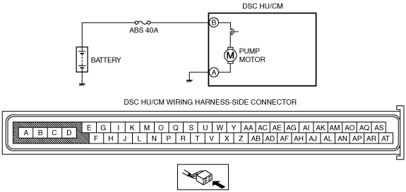
•  ABS 40A fuse malfunction
•  Open or short to ground circuit in the wiring harness between the battery and the DSC HU/CM terminal B
•  Open circuit in the wiring harness between the DSC HU/CM terminal A and the body ground
•  Open or short circuit in the DSC HU/CM internal motor relay, or stuck motor relay
•  Open or short circuit in the DSC HU/CM internal motor, or frozen motor
•  Poor connection at connectors (female terminal)

Diagnostic procedure

STEP

INSPECTION

ACTION

1
INSPECT FUSE CONDITION
•  Is the ABS 40A fuse normal?
Yes
Go to the next step.
No
Replace the fuse, then go to Step 5.
2
INSPECT MOTOR RELAY POWER SUPPLY FOR OPEN CIRCUIT
•  Turn the ignition switch to the LOCK position.
•  Disconnect DSC HU/CM connector.
•  Turn the ignition switch to the ON position (engine off).
•  Measure voltage between DSC HU/CM terminal B (harness-side) and ground.
•  Is the voltage B+?
Yes
Go to the next step.
No
Repair or replace the wiring harness for open circuit between battery positive terminal and DSC HU/CM terminal B, then go to Step 5.
3
INSPECT PUMP MOTOR GROUND FOR OPEN CIRCUIT
•  Turn the ignition switch to the LOCK position.
•  Inspect for continuity between DSC HU/CM terminal A (harness-side) and ground.
•  Is there continuity?
Yes
Go to the next step.
No
Repair or replace the wiring harness for open circuit between DSC HU/CM terminal A and ground, then go to Step 5.
4
VERIFY PUMP MOTOR OPERATION
•  Turn the ignition switch to the LOCK position.
•  Connect the M-MDS to the DLC-2.
•  Turn the ignition switch to the ON position (engine off).
•  Access PMP_MOTOR active command modes using M-MDS.
•  Does the pump motor operate?
Yes
Go to the next step.
No
Replace the DSC HU/CM, then go to the next step.
5
VERIFY TROUBLESHOOTING COMPLETED
•  Make sure to reconnect all disconnected connectors.
•  Clear the DTC from the memory.
•  Start the engine and drive the vehicle at 10 km/h {6.2 mph} or more.
•  Gradually slow down and stop the vehicle.
•  Is the same DTC present?
Yes
Replace the DSC HU/CM, then go to the next step.
No
Go to the next step.
6
VERIFY AFTER REPAIR PROCEDURE
•  Are any other DTCs present?
Yes
Go to the applicable DTC inspection.
No
DTC troubleshooting completed.