DTC C1279, C1280, C1281, C1952, C1959 [DYNAMIC STABILITY CONTROL (DSC)]


id0402b2887300

DTC
C1279, C1280, C1281, C1952, C1959
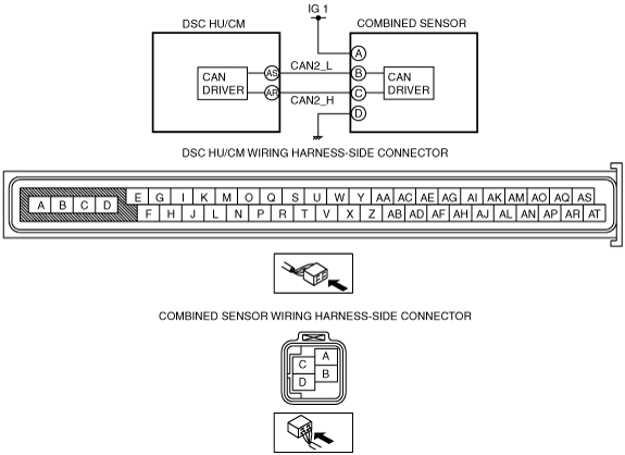
Combined sensor system
DETECTION CONDITION
•  C1279
―  Variation of the yaw rate value from the combined sensor while the vehicle is stopped or started is not within the specification.
•  C1280
―  Condition 1
•  The difference between the yaw rate value calculated by each sensor and the yaw rate value from the combined sensor exceeds the specification.
―  Condition 2
•  While the vehicle is moving forward, one of the yaw rate values is + and the other is - (yaw rate value calculated from steering angle sensor signal and one from the combined sensor).
•  C1281
―  Difference between the two lateral-G values exceeds the specification (one from the combined sensor and one calculated from yaw rate signal from the combined sensor, steering angle sensor signal, and ABS wheel-speed sensor signal).
•  C1952
―  Signal, which indicates low voltage or over voltage, from the combined sensor is continued for 100 ms.
•  C1959
―  Variation of the lateral-G value from the combined sensor is not within the specification.
POSSIBLE CAUSE
•  Poor installation of combined sensor
•  Open circuit or short to ground in wiring harness between ignition switch—combined sensor terminal A
•  Open circuit in wiring harness between combined sensor terminal D—ground
•  Combined sensor malfunction
•  Poor connection at connectors (female terminal)

Diagnostic procedure

STEP

INSPECTION

ACTION

1
INSPECT COMBINED SENSOR INSTALLATION CONDITION
•  Inspect the installation condition of the combined sensor.
•  Is the combined sensor installed correctly?
Yes
Go to the next step.
No
Install the combined sensor correctly, then go to the next step.
2
INSPECT COMBINED SENSOR POWER SUPPLY FOR OPEN OR SHORT CIRCUIT
•  Turn the ignition switch to the ON position.
•  Measure the voltage between combined sensor terminal A and body ground.
•  Is the voltage approx. 12 V?
Yes
Go to the next step.
No
Repair or replace the wiring harness, then go to Step 5.
3
INSPECT COMBINED SENSOR GROUND FOR OPEN CIRCUIT
•  Turn the ignition switch to the LOCK position.
•  Inspect for continuity between combined sensor terminal D and body ground.
•  Is there continuity?
Yes
Go to the next step.
No
Repair or replace the wiring harness, then go to Step 5.
4
INSPECT COMBINED SENSOR
•  Inspect the combined sensor.
•  Is the combined sensor normal?
Yes
Go to the next step.
No
Replace the combined sensor, then go to the next step.
5
VERIFY DTC TROUBLESHOOTING COMPLETED
•  Clear the DTC from the memory.
•  Start the engine and drive the vehicle at 10 km/h {6.0 mph} or more.
•  Are the same DTCs present?
Yes
Replace the DSC HU/CM, then go to the next step.
No
Go to the next step.
6
VERIFY AFTER REPAIR PROCEDURE
•  Are any other DTCs present?
Yes
Go to the applicable DTC inspection.
No
DTC troubleshooting completed.