 |
amxzzw00000249
POWER BRAKE UNIT REMOVAL/INSTALLATION
id041100801800
1. For 6MT vehicles (L.H.D.), perform the following procedures:
2. Remove the master cylinder. (See MASTER CYLINDER REMOVAL/INSTALLATION.)
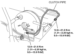
3. For MT vehicles (L.H.D.), remove the clutch pipe as shown in the figure.
amxzzw00000249
|
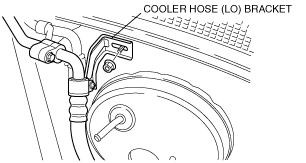
4. For L.H.D., remove the nut as shown in the figure, then remove the cooler hose (LO) bracket from the vehicle.
amxzzw00000250
|
5. Remove in the order indicated in the table.
6. Remove the brake switch. (See BRAKE PEDAL REMOVAL/INSTALLATION.)
7. Install in the reverse order of removal.
8. After installation, perform brake pedal inspection. (See BRAKE PEDAL INSPECTION.)
amxzzw00000251
|
|
1
|
Vacuum hose
|
|
2
|
Snap pin
|
|
3
|
Clevis pin
|
|
4
|
Nut
|
|
5
|
Power brake unit
|
|
6
|
Gasket
|
|
7
|
Fork
|
|
8
|
Locknut
|