 |
amxzzw00000133
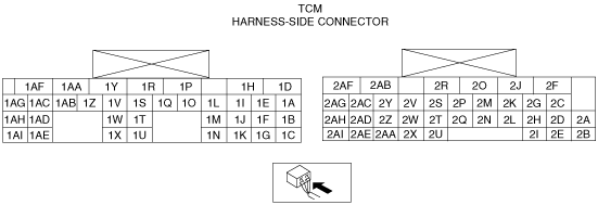
TCM INSPECTION [SJ6A-EL]
id051311250700
Terminal Voltage Table (Reference)
amxzzw00000133
|
|
Terminal |
Signal |
Connected to |
Test Condition |
Voltage (V) |
Action |
|---|---|---|---|---|---|
|
1A
|
—
|
—
|
—
|
—
|
—
|
|
1B
|
—
|
—
|
—
|
—
|
—
|
|
1C
|
CAN_L
|
Other module
|
Because this terminal is for serial communication, good/no good judgment by terminal voltage is not possible. Carry out inspection according to DTCs.
|
• Inspect the related wiring harness
|
|
|
1D
|
TCC control solenoid GND
|
TCC control solenoid
|
• Inspect using the wave profile.
|
• Inspect the TCC control solenoid
• Inspect the related wiring harness
|
|
|
1E
|
Line pressure control solenoid GND
|
Line pressure control solenoid
|
P, N position, Idle
|
Below 1.0
|
• Inspect the line pressure control solenoid
• Inspect the related wiring harness
|
|
1F
|
—
|
—
|
—
|
—
|
—
|
|
1G
|
CAN_H
|
Other module
|
Because this terminal is for serial communication, good/no good judgment by terminal voltage is not possible. Carry out inspection according to DTCs.
|
• Inspect the related wiring harness
|
|
|
1H
|
—
|
—
|
—
|
—
|
—
|
|
1I
|
—
|
—
|
—
|
—
|
—
|
|
1J
|
ATF temperature (+)
|
TFT sensor
|
ATF temperature 20°C {68°F}
|
Approx. 3.0
|
• Inspect the TFT sensor
• Inspect the related wiring harness
|
|
ATF temperature 40°C {104°F}
|
Approx. 2.14
|
||||
|
ATF temperature 60°C {140°F}
|
Approx. 1.38
|
||||
|
1K
|
—
|
—
|
—
|
—
|
—
|
|
1L
|
Shift solenoid G GND
|
Shift solenoid G
|
• Inspect using the wave profile.
|
• Inspect the shift solenoid G
• Inspect the related wiring harness
|
|
|
1M
|
TFT sensor GND
|
TFT sensor
|
Under any condition
|
Continuity
|
• Inspect the related wiring harness
|
|
1N
|
—
|
—
|
—
|
—
|
—
|
|
1O
|
Shift solenoid F GND
|
Shift solenoid F
|
• Inspect using the wave profile.
|
• Inspect the shift solenoid F
• Inspect the related wiring harness
|
|
|
1P
|
System GND
|
GND
|
Under any condition
|
Continuity
|
• Inspect the related wiring harness
|
|
1Q
|
TCC control solenoid control
|
TCC control solenoid
|
• Inspect using the wave profile.
|
• Inspect the TCC control solenoid
• Inspect the related wiring harness
|
|
|
1R
|
Line pressure control solenoid control
|
Line pressure control solenoid
|
• Inspect using the wave profile.
|
• Inspect the line pressure control solenoid
• Inspect the related wiring harness
|
|
|
1S
|
Shift solenoid D control
|
Shift solenoid D
|
5GR, 6GR
|
B+
|
• Inspect the shift solenoid D
• Inspect the related wiring harness
|
|
1GR, 2GR, 3GR, 4GR
|
Below 1.0
|
||||
|
1T
|
—
|
—
|
—
|
—
|
—
|
|
1U
|
—
|
—
|
—
|
—
|
—
|
|
1V
|
Shift solenoid E control
|
Shift solenoid E
|
1GR, 2GR, 3GR, 4GR
|
B+
|
• Inspect the shift solenoid E
• Inspect the related wiring harness
|
|
5GR, 6GR
|
Below 1.0
|
||||
|
1W
|
—
|
—
|
—
|
—
|
—
|
|
1X
|
System GND
|
GND
|
Under any condition
|
Continuity
|
• Inspect the related wiring harness
|
|
1Y
|
Shift solenoid G control
|
Shift solenoid G
|
• Inspect using the wave profile.
|
• Inspect the shift solenoid G
• Inspect the related wiring harness
|
|
|
1Z
|
Shift solenoid F control
|
Shift solenoid F
|
• Inspect using the wave profile.
|
• Inspect the shift solenoid F
• Inspect the related wiring harness
|
|
|
1AA
|
Shift solenoid C control
|
Shift solenoid C
|
1GR, 2GR, 3GR
|
B+
|
• Inspect the shift solenoid C
• Inspect the related wiring harness
|
|
4GR, 5GR, 6GR
|
Below 1.0
|
||||
|
1AB
|
Shift solenoid B control
|
Shift solenoid B
|
1GR, 2GR, 6GR
|
B+
|
• Inspect the shift solenoid B
• Inspect the related wiring harness
|
|
3GR, 4GR, 5GR
|
Below 1.0
|
||||
|
1AC
|
—
|
—
|
—
|
—
|
—
|
|
1AD
|
Power supply
|
Battery
|
Under any condition
|
B+
|
• Inspect the related wiring harness
|
|
1AE
|
IG
|
Ignition switch
|
Ignition switch ON
|
B+
|
• Inspect the Ignition switch
• Inspect the related wiring harness
|
|
Ignition switch OFF
|
Below 1.0
|
||||
|
1AF
|
Shift solenoid A control
|
Shift solenoid A
|
2GR, 3GR, 4GR, 5GR, 6GR
|
B+
|
• Inspect the shift solenoid A
• Inspect the related wiring harness
|
|
1GR
|
Below 1.0
|
||||
|
1AG
|
—
|
—
|
—
|
—
|
—
|
|
1AH
|
—
|
—
|
—
|
—
|
—
|
|
1AI
|
IG
|
Ignition switch
|
Ignition switch ON
|
B+
|
• Inspect the Ignition switch
• Inspect the related wiring harness
|
|
Ignition switch OFF
|
Below 1.0
|
||||
|
2A
|
Turbine speed (+)
|
Turbine sensor
|
• Inspect using the wave profile.
|
• Inspect the turbine sensor
• Inspect the related wiring harness
|
|
|
2B
|
Turbine speed (-)
|
Turbine sensor
|
Ignition switch ON
|
Approx. 2.54
|
• Inspect the turbine sensor
• Inspect the related wiring harness
|
|
2C
|
Vehicle speed (-)
|
VSS
|
Ignition switch ON
|
Approx. 2.5
|
• Inspect the VSS
• Inspect the related wiring harness
|
|
2D
|
Vehicle speed (+)
|
VSS
|
• Inspect using the wave profile.
|
• Inspect the VSS
• Inspect the related wiring harness
|
|
|
2E
|
Turbine sensor wiring harness shield GND
|
GND
|
Under any condition
|
Continuity
|
• Inspect the related wiring harness
|
|
2F
|
Down switch
(Selector lever component)
|
Down switch
(Selector lever component)
|
Shift down
(M range)
|
Below 1.0
|
• Inspect the selector lever component
• Inspect the related wiring harness
|
|
Other ranges, all positions
|
B+
|
||||
|
2G
|
M range switch
|
M range switch
|
M range
|
Below 1.0
|
• Inspect the selector lever component
• Inspect the related wiring harness
|
|
Other positions, all ranges
|
B+
|
||||
|
2H
|
VSS wiring harness shield GND
|
GND
|
Under any condition
|
Continuity
|
• Inspect the related wiring harness
|
|
2I
|
—
|
—
|
—
|
—
|
—
|
|
2J
|
Up switch
(Selector lever component)
|
Up switch
(Selector lever component)
|
Shift up
(M range)
|
Below 1.0
|
• Inspect the selector lever component
• Inspect the related wiring harness
|
|
Other ranges, all positions
|
B+
|
||||
|
2K
|
TR switch
(D range)
|
TR switch
|
D range
|
B+
|
• Inspect the TR switch
• Inspect the related wiring harness
|
|
Other ranges, all positions
|
Below 1.0
|
||||
|
2L
|
—
|
—
|
—
|
—
|
—
|
|
2M
|
TR switch
(R position)
|
TR switch
|
R position
|
B+
|
• Inspect the TR switch
• Inspect the related wiring harness
|
|
Other ranges, all positions
|
Below 1.0
|
||||
|
2N
|
TR switch
(N position)
|
TR switch
|
N position
|
B+
|
• Inspect the TR switch
• Inspect the related wiring harness
|
|
Other positions, all ranges
|
Below 1.0
|
||||
|
2O
|
TR switch
(P position)
|
TR switch
|
P position
|
B+
|
• Inspect the TR switch
• Inspect the related wiring harness
|
|
Other positions, all ranges
|
Below 1.0
|
||||
|
2P
|
—
|
—
|
—
|
—
|
—
|
|
2Q
|
ATF temperature monitor mode control
|
TFT check connector
|
Under any condition
|
B+
|
• Inspect the related wiring harness
|
|
2R
|
—
|
—
|
—
|
—
|
—
|
|
2S
|
—
|
—
|
—
|
—
|
—
|
|
2T
|
—
|
—
|
—
|
—
|
—
|
|
2U
|
—
|
—
|
—
|
—
|
—
|
|
2V
|
—
|
—
|
—
|
—
|
—
|
|
2W
|
—
|
—
|
—
|
—
|
—
|
|
2X
|
—
|
—
|
—
|
—
|
—
|
|
2Y
|
—
|
—
|
—
|
—
|
—
|
|
2Z
|
—
|
—
|
—
|
—
|
—
|
|
2AA
|
—
|
—
|
—
|
—
|
—
|
|
2AB*1
|
Steering shift switch GND
|
Steering shift switch
|
Under any condition
|
Below 1.0
|
• Inspect the related wiring harness
|
|
2AB*2
|
—
|
Audio control switch
|
Under any condition
|
Below 1.0
|
• Inspect the related wiring harness
|
|
2AC
|
—
|
—
|
—
|
—
|
—
|
|
2AD
|
—
|
—
|
—
|
—
|
—
|
|
2AE
|
—
|
—
|
—
|
—
|
—
|
|
2AF*1
|
Shift up/Shift down signal
(Steering shift switch)
|
Steering shift switch
|
Up switch operated
(Steering shift switch)
|
Approx. 2.0
|
• Inspect the steering shift switch
• Inspect the related wiring harness
|
|
Down switch operated
(Steering shift switch)
|
Approx. 2.53
|
||||
|
Others
|
Approx. 4.0
|
||||
|
2AF*2
|
—
|
Audio control switch
|
Under any condition
|
Below 1.0
|
• Inspect the audio control switch
• Inspect the related wiring harness
|
|
2AG
|
—
|
—
|
—
|
—
|
—
|
|
2AH
|
—
|
—
|
—
|
—
|
—
|
|
2AI
|
—
|
—
|
—
|
—
|
—
|
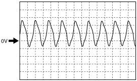
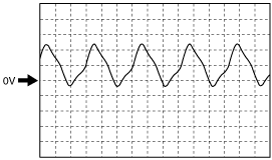
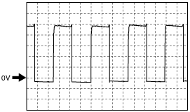
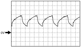
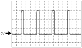
Inspection Using An Oscilloscope (Reference)
Turbine sensor (+)
amxzzw00000134
|
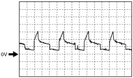
Vehicle speed (+)
amxzzw00000135
|
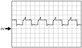
Shift solenoid F control (+)
amxzzw00002523
|
Shift solenoid F control (-)
amxzzw00000137
|
Shift solenoid G control (+)
amxzzw00000138
|
Shift solenoid G control (-)
amxzzw00000139
|
TCC control solenoid control (+)
amxzzw00002524
|
TCC control solenoid control (-)
amxzzw00002525
|
Line pressure control solenoid control (+)
amxzzw00002526
|