|
amxzzw00000149
CONTROL VALVE BODY REMOVAL [SJ6A-EL]
id051311710600
On-Vehicle Removal
1. Remove the battery cover.
2. Disconnect the negative battery cable. (See BATTERY REMOVAL/INSTALLATION [L8, LF].)
3. Drain the ATF. (See AUTOMATIC TRANSMISSION FLUID (ATF) REPLACEMENT [SJ6A-EL].)
4. Remove the oil pan and the oil pan gasket.
5. Remove the magnets from the oil pan.
amxzzw00000149
|
6. Remove the oil strainer from the control valve body component.
e5u513zw5048
|
7. Remove the O-ring from the oil strainer.
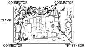
8. Disconnect the connectors from the solenoids.
amxzzw00000773
|
9. Disconnect the coupler component from the clamps.
10. Remove the lock plate from the control valve body component.
e5u513zw5067
|
11. Pull the TFT sensor from the control valve body component.
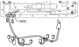
12. Fix the coupler component with tape to the transmission case as shown in the figure.
e5u513zw5050
|
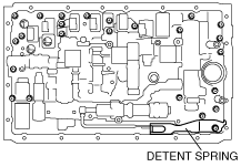
13. Remove the detent spring cover and detent spring from the control valve body component.
e5u513zw5047
|
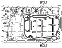
14. Remove the bolts from the transmission case as shown in the figure.
amxzzw00000150
|
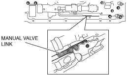
15. Disconnect the manual valve link and remove the control valve body component.
e5u513zw5072
|
16. Remove the check valve sub-component and the compression spring from the transmission case.
amxzzw00000151
|
17. Remove the transmission case gaskets and the brake drum gaskets from the transmission case.
amxzzw00000152
|
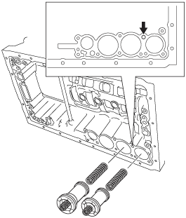
18. Apply compressed air into the oil passage as shown in the figure and remove the accumulator pistons (C-2, B-3) and the compression springs from the transmission case.
amxzzw00000153
|
19. Remove the snap rings from the accumulator pistons (C-2, B-3) using a flathead screwdriver.
20. Remove the compression springs from the accumulator pistons (C-2, B-3).
21. Remove the O-rings from the accumulator pistons (C-2, B-3) using a flathead screwdriver.
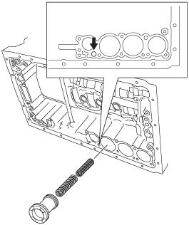
22. Apply compressed air into the oil passage as shown in the figure and remove the accumulator piston (C-3) and compression springs from the transmission case.
amxzzw00000154
|
23. Remove the O-rings from the accumulator piston (C-3) using a flathead screwdriver.
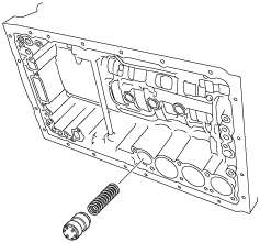
24. Remove the accumulator valve and compression springs from the transmission case.
amxzzw00000155
|