 |
amxzzw00001130
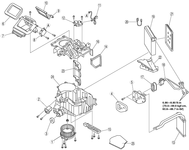
A/C UNIT DISASSEMBLY/ASSEMBLY
id071100800300
1. Disassemble in the order indicated in the table.
2. Assemble in the reverse order of disassembly.
L.H.D.
amxzzw00001130
|
R.H.D.
amxzzw00001131
|
|
1
|
Blower motor
|
|
2
|
Power MOS FET
|
|
3
|
Polyurethane foam (1)
|
|
4
|
Polyurethane foam (2)
|
|
5
|
Cover (1)
|
|
6
|
Adhesive polyurethane (1)
|
|
7
|
Air intake box
|
|
8
|
Air intake actuator
|
|
9
|
Air intake crank
|
|
10
|
Air intake door
|
|
11
|
Harness
|
|
12
|
Air mix actuator
|
|
13
|
Heater core
|
|
14
|
Adhesive polyurethane (2)
|
|
15
|
Cover (2) (L.H.D.)
|
|
16
|
A/C case (1)
|
|
17
|
Cover (3)
|
|
18
|
Expansion valve
|
|
19
|
Evaporator
|
|
20
|
Evaporator temperature sensor
|
|
21
|
Cover (4)
|
|
22
|
Insulator (1)
|
|
23
|
Air mix damper
|
|
24
|
A/C case (2)
|
|
25
|
Insulator (2)
|
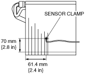
Evaporator Temperature Sensor Assembly Note
1. Assemble the evaporator temperature sensor as shown in the figure.
L.H.D.
e5u711zw5005
|
R.H.D.
amxzzw00000681
|