 |
amxzzw00001939
DTC B1916, B1932, B1934, B1936 [AIR BAG SYSTEM]
id0802a0810200
System Malfunction Location
|
DTC |
System Malfunction Location |
|---|---|
|
M-MDS display |
|
|
B1916
|
Driver-side air bag module circuit short to power supply
|
|
B1932
|
Driver-side air bag module circuit open circuit or resistance high
|
|
B1934
|
Driver-side air bag module circuit resistance low
|
|
B1936
|
Driver-side air bag module circuit short to body ground
|
Detection Condition
Possible Causes
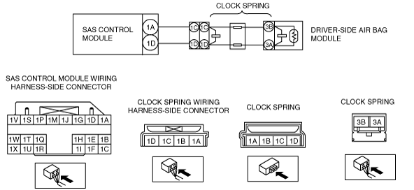
System Wiring Diagram
amxzzw00001939
|
Diagnostic Procedure
|
STEP |
INSPECTION |
ACTION |
|
|---|---|---|---|
|
1
|
INSPECT DRIVER-SIDE AIR BAG MODULE CONNECTOR (CLOCK SPRING)
• Turn the ignition switch to the LOCK position.
• Disconnect the negative battery cable and wait for 1min or more.
• Remove the driver-side air bag module.
• Inspect the clock spring connector. (Corrosion, damage, and disconnected pins)
• Is there any malfunction of the clock spring connector?
|
Yes
|
Replace the clock spring.
|
|
No
|
Go to the next step.
|
||
|
2
|
INSPECT CLOCK SPRING
• Remove the steering wheel.
• Remove the column cover.
• Remove the clock spring.
• Inspect for continuity between clock spring connector terminals 1C—3B and 1D—3A.
• Is there continuity?
|
Yes
|
Go to the next step.
|
|
No
|
Replace the clock spring.
|
||
|
3
|
INSPECT WIRING HARNESS BETWEEN SAS CONTROL MODULE AND CLOCK SPRING
• Remove the glove compartment.
• Disconnect the passenger-side air bag module connector.
• Disconnect the driver and passenger-side seat connectors.
(See SEAT REMOVAL/INSTALLATION.)
• Remove the back trim.
• Remove the driver and passenger-side pre-tensioner seat belt connectors.
• Remove the console panel.
• Disconnect the SAS control module connectors.
• Inspect the wiring harness between SAS control module connector terminal 1A and clock spring connector terminal 1C, and SAS control module connector terminal 1D and clock spring connector terminal 1D for the following:
• Is the wiring harness normal?
|
Yes
|
Go to the next step.
|
|
No
|
Replace the wiring harness between the SAS control module and clock spring.
|
||
|
4
|
INSPECT THE WIRING HARNESS BETWEEN THE SAS CONTROL MODULE AND DRIVER-SIDE AIR BAG MODULE FOR A SHORT CIRCUIT TO THE POWER SUPPLY
• Connect the negative battery cable.
• Turn the ignition switch to the ON position with SAS control module connector and clock spring connector disconnected.
• Measure the voltage of SAS control module connector terminals 1A and 1D.
• Is the voltage measured?
|
Yes
|
Replace the wiring harness between the SAS control module and clock spring.
|
|
No
|
Go to the next step.
|
||
|
5
|
INSPECT DRIVER-SIDE AIR BAG MODULE
• Connect the leads of the SST (Fuel and thermometer checker) or apply 2 ohms resistance to clock spring connector terminals 3A and 3B.
• Set the resistance of the SST (Fuel and thermometer checker) to the 2 ohms position.
• Except for the driver-side air bag module connector, reconnect all disconnected connectors.
• Connect the negative battery cable.
• Turn the ignition switch to the ON position.
• Clear DTCs using the M-MDS.
• Perform the DTC inspection for the SAS control module using the M-MDS.
• Are the same DTCs present?
|
Yes
|
Go to the next step.
|
|
No
|
Replace the driver-side air bag module.
|
||
|
6
|
PERFORM SAS CONTROL MODULE DTC INSPECTION
• Turn the ignition switch to the LOCK position.
• Disconnect the negative battery cable and wait for 1min or more.
• Disconnect the SST (Fuel and thermometer checker) or the 2 ohms resistance.
• Connect the driver-side air bag module connector.
• Connect the negative battery cable.
• Turn the ignition switch to the ON position.
• Clear the DTC for the SAS control module using the M-MDS.
• Perform the DTC inspection for the SAS control module using the M-MDS.
• Are the same DTCs present?
|
Yes
|
Replace the SAS control module.
|
|
No
|
DTC troubleshooting completed.
|
||