 |
amxzzw00001585
DETERMINING MALFUNCTIONING PART (HS-CAN) [MULTIPLEX COMMUNICATION SYSTEM (L.H.D.)]
id0902j3846700
1. Verify the CAN system-related module DTCs and the failed module on the M-MDS screen.
2. Refer to “DTC Output Pattern and Malfunctioning Part” and find the area linked from the malfunctioning part.
3. Inspect the possible cause and inspection item of the applicable malfunctioning part.
4. Perform the DTC inspection after the repair procedure.
DTC Output Pattern and Malfunctioning Part
|
M-MDS display |
DTC output pattern and malfunctioning part |
|||||||||||||
|---|---|---|---|---|---|---|---|---|---|---|---|---|---|---|
|
DTC output module |
DTC |
|||||||||||||
|
PCM
(PCM)
|
U0101
|
|
×
|
|
|
|
|
|
|
|
|
|
|
|
|
U0121
|
|
|
|
×
|
×
|
|
|
|
|
|
|
|
|
|
|
U0155
|
|
|
|
|
|
|
|
|
|
|
|
|
×
|
|
|
TCM*1
(TCM)
|
U0100
|
×
|
|
|
|
|
|
|
|
|
|
|
|
|
|
ABS*2
(ABS HU/CM)
|
U2023
|
-
|
|
-
|
|
|
|
|
|
|
|
|
|
|
|
ABS*3
(DSC HU/CM)
|
U0100
|
×
|
|
×
|
|
|
|
|
|
|
|
|
|
|
|
U0101
|
|
×
|
×
|
|
|
|
|
|
|
|
|
|
|
|
|
U0155
|
|
|
|
|
|
|
|
|
|
|
|
|
×
|
|
|
U2023
|
-
|
|
-
|
|
|
|
|
|
|
|
|
|
|
|
|
RHT*4
(Power retractable hardtop control module)
|
U0100
|
×
|
|
×
|
|
|
×
|
|
|
|
|
|
|
|
|
U0101
|
|
×
|
×
|
|
|
×
|
|
|
|
|
|
|
|
|
|
U2197
|
-
|
|
-
|
|
|
-
|
|
|
|
|
|
|
|
|
|
DHS*5
(Active bonnet control module)
|
U0155:00
|
|
|
|
|
|
|
|
|
|
|
|
|
×
|
|
IC
(Instrument cluster)
|
U0100
|
×
|
|
×
|
|
|
×
|
|
×
|
|
×
|
|
×
|
|
|
U0101
|
|
×
|
×
|
|
|
×
|
|
×
|
|
×
|
|
×
|
|
|
|
U0121
|
|
|
|
×
|
×
|
×
|
|
×
|
|
×
|
|
×
|
|
|
|
U0207
|
|
|
|
|
|
|
×
|
×
|
|
×
|
|
×
|
|
|
|
U0214
|
|
|
|
|
|
|
|
|
|
|
×
|
×
|
|
|
|
U0250
|
|
|
|
|
|
|
|
|
×
|
×
|
|
×
|
|
|
|
U2023
|
-
|
|
-
|
|
|
-
|
|
-
|
|
-
|
|
-
|
|
|
|
U2197
|
-
|
|
-
|
|
|
-
|
|
-
|
|
-
|
|
-
|
|
|
|
M-MDS display module
|
“Fail” display pattern
|
|
|
|
|
|
||||||||
|
PCM
|
×
|
|
×
|
|
|
×
|
|
×
|
|
×
|
|
×
|
|
|
|
TCM*1
|
|
×
|
×
|
|
|
×
|
|
×
|
|
×
|
|
×
|
|
|
|
ABS*2, *3
|
|
|
|
×
|
×
|
×
|
|
×
|
|
×
|
|
×
|
|
|
|
RHT*4
|
|
|
|
|
|
|
×
|
×
|
|
×
|
|
×
|
|
|
|
DHS*5
|
|
|
|
|
|
|
|
|
×
|
×
|
|
×
|
|
|
|
IC
|
|
|
|
|
|
|
|
|
|
|
|
|
×
|
|
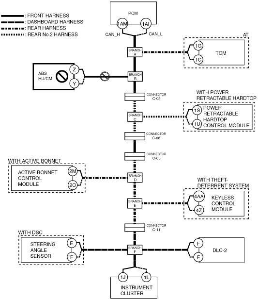
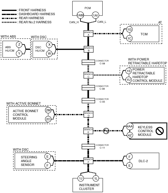
A
Possible cause
System wiring diagram
amxzzw00001585
|
Inspection item
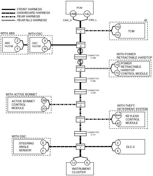
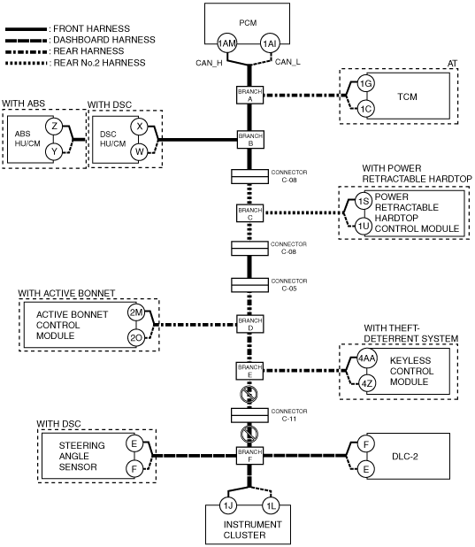
B
Possible cause
System wiring diagram
amxzzw00001586
|
Inspection item
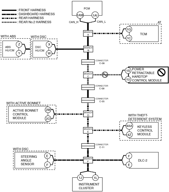
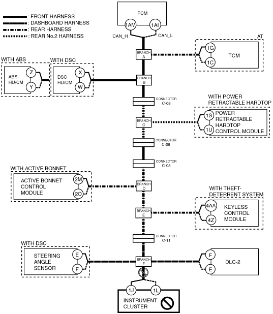
C
Possible cause
System wiring diagram
amxzzw00001587
|
Inspection item
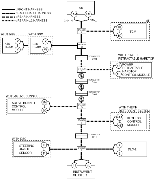
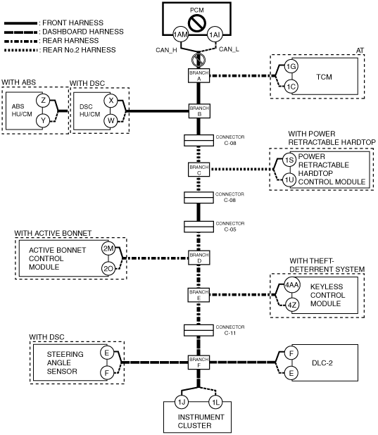
D
Possible cause
System wiring diagram
amxzzw00001588
|
Inspection item
E
Possible cause
System wiring diagram
amxzzw00001589
|
Inspection item
F
Possible cause
System wiring diagram
amxzzw00001590
|
Inspection item
G
Possible cause
System wiring diagram
amxzzw00001591
|
Inspection item
H
Possible cause
System wiring diagram
amxzzw00001592
|
Inspection item
I
Possible cause
System wiring diagram
amxzzw00002639
|
Inspection item
J
Possible cause
System wiring diagram
amxzzw00002640
|
Inspection item
K
Possible cause
System wiring diagram
amxzzw00001593
|
Inspection item
L
Possible cause
System wiring diagram
amxzzw00001594
|
Inspection item
M
Possible cause
System wiring diagram
amxzzw00001595
|
Inspection item