ON-BOARD DIAGNOSTIC SYSTEM FUNCTION [AUDIO SYSTEM]


id0920001018a1

•  The on-board diagnostic system has a self-diagnostic function and diagnostic assist function to help technicians locate malfunctions.

Self-diagnostic Function


Malfunction detection function

•  The malfunction detection function detects malfunctions occurring in the audio system.


Memory function

•  The memory function detects a malfunction, changes it to a DTC, and stores it in the memory. The memory can store a maximum of three DTCs. If another malfunction is detected when three DTCs are already stored, the memory function clears the oldest DTC and stores the new one.
•  Once a DTC is stored, it can only be cleared by the designated procedure; not by turning the ignition switch to the LOCK position or disconnecting the negative battery cable. The procedure is mentioned in the Workshop Manual.


Display function

•  When the self-diagnostic function is activated, the information display displays the DTC stored in the memory.
•  The DTC consists of the following codes:
―  Supplier code (indicates manufacturer)
―  Device code (indicates malfunctioning part)
―  Error code (indicates malfunction description)
•  Refer to the Workshop Manual for the display method.
amxzzn00000306

Supplier code

Supplier name

01
SANYO Automedia
02
Panasonic
03
Clarion
04
Pioneer
05
VISTEON

Device code

Parts name

09
Audio unit
10
MP3/WMA (windows media audio) applicable CD player
16
CAN system
21
Center panel
22
MP3/WMA (windows media audio) applicable CD changer

Error code

Malfunction description

01
Internal mechanism error
02
Servo mechanism error
07
Disc reading error
12
CAN line (communication line) error
17
Incorrect combination
18
Incorrect combination
19
Communication line
20
Insufficient power supply
21
Amplifier related circuit
22
Tuner error

Screen display

Malfunction location

DTC

Output signal

09: Er20
Power supply circuit to audio unit
09: Er21
•  Speaker or speaker circuit
•  Audio unit (peripheral circuit for power amplifier)
09: Er22
Audio unit (peripheral circuit for tuner)
10: Er01
MP3/WMA (windows media audio) applicable CD player system
10: Er02
CHECK CD
MP3/WMA (windows media audio) applicable CD player system
10: Er07
CHECK CD
MP3/WMA (windows media audio) applicable CD player system
16: Er12
CAN system communication error
21: Er17
Communication error between center panel and audio unit
21: Er18
Communication error between center panel and audio unit
21: Er19
Communication error between center panel and audio unit
22: Er01
MP3/WMA (windows media audio) applicable CD changer system
22: Er02
CHECK CD
MP3/WMA (windows media audio) applicable CD changer system
22: Er07
CHECK CD
MP3/WMA (windows media audio) applicable CD changer system
no Err
No DTCs stored


Diagnostic Assist Function
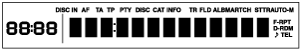
•  The diagnostic assist function displays the operating condition of the following functions (components) and forces them to operate in order to examine whether they are malfunctioning or not.
•  For the start procedure of each mode, refer to the Workshop Manual.

Display

•  Illuminates all the characters on the display and checks if they are not truncated or faint.
amxzzn00000307


Switch

•  Activates a buzzer sound, switch name or dial rotation direction when a switch is operated and examines each of the switches.
amxzzn00000308


Speaker

•  Verifies that the speakers output sound in the following order and examines the speakers and wiring harness between the audio unit and speaker.
Without Bose®
―   Door speaker (LH) and tweeter (LH)
―   Door speaker (RH) and tweeter (RH)
―   Rear speaker (RH) (with 6 speaker type)
―   Rear speaker (LH) (with 6 speaker type)
With Bose®
―   Door speaker (LH) and door upper speaker (LH) and center speaker
―   Door speaker (RH) and door upper speaker (RH) and center speaker
―   Rear speaker


Radio

•  The diagnostic assist function displays the radio reception condition in 11 levels (0—10) to assist in determining the condition of the antenna, antenna feeders, and audio unit (tuner).
amxzzn00000309


Antenna control condition

•  The diagnostic assist function displays the output state of the antenna amplifier power supply to determine the condition of the antenna amplifier, audio unit, and wiring harness between the audio unit and antenna amplifier.
amxzzn00000310


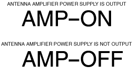
Audio Amplifier control condition

•  The diagnostic assist function displays the output state of the audio amplifier operating signal to determine the condition of the audio amplifier, audio unit, and wiring harness between the audio unit and audio amplifier.
amxzzn00000311


Center panel

•  Displays the destination code of the center panel on the display and examines the destination of the center panel.
amxzzn00000312


Audio amplifier specification

•  Displays the audio amplifier specification on the display screen to verify its specification.
amxzzn00000313


Audio amplifier (with Bose®) identify inspection

•  Inspection of the audio amplifier can be performed by operating the following speakers.
With standard seat
―  Rear speaker
With leather seat
―  Door speaker