 |
am3zzn00000547
ON-BOARD DIAGNOSTIC SYSTEM TEST MODE [MZ-CD 1.6 (Y6)]
id0102c3100200
|
Diagnostic test mode |
Item |
|---|---|
|
Mode 01
|
Sending diagnostic data (PID data monitor/On-board system readiness test)
|
|
Mode 02
|
Sending freeze frame data
|
|
Mode 03
|
Sending emission-related malfunction code (DTC)
|
|
Mode 04
|
Clearing/resetting emission-related malfunction information
|
|
Mode 06
|
Sending intermittent monitoring system test results (DMTR)
|
|
Mode 07
|
Sending continuous monitoring system test results (pending code)
|
|
Mode 09
|
Request vehicle information
|
Sending Diagnostic Data (Mode 01)
PID data monitor
PID/DATA monitor item table
|
Full names |
Unit |
|
|---|---|---|
|
Monitor status since DTCs cleared
|
No unit
|
|
|
LOAD
|
%
|
|
|
ECT
|
°C
|
°F
|
|
MAP
|
kPa
|
|
|
Engine speed
|
rpm
|
|
|
Vehicle speed
|
km/h
|
mph
|
|
IAT
|
°C
|
°F
|
|
MAF
|
g/s
|
|
|
OBD requirement according to vehicle design
|
No unit
|
|
|
Time since engine start
|
s
|
|
|
Distance travelled while MIL is activated
|
km/h
|
mph
|
|
Fuel rail pressure
|
kPa
|
|
|
EGR valve control signal
|
%
|
|
|
EGR error
|
%
|
|
|
Number of warm-ups since DTCs cleared
|
Warm up
|
|
|
Distance travelled since DTCs cleared
|
km/h
|
mph
|
|
Barometric pressure
|
kPa
|
|
|
Catalyst exhaust gas temperature sensor No.1
|
°C
|
°F
|
|
Catalyst exhaust gas temperature sensor No.2
|
°C
|
°F
|
|
Monitor status this driving cycle
|
No unit
|
|
|
PCM voltage
|
V
|
|
|
APP
|
%
|
|
|
Throttle actuator control signal
|
%
|
|
Sending Freeze Frame Data/ Snapshot Data
Freeze frame data table
|
Freeze frame data item |
Unit |
Description |
Corresponding PID data monitor item |
|---|---|---|---|
|
LOAD
|
%
|
Calculated engine load
|
LOAD
|
|
ECT
|
°C
|
Engine coolant temperature
|
ECT
|
|
MAP
|
Pa
|
Manifold absolute pressure
|
MAP
|
|
RPM
|
RPM
|
Engine speed
|
RPM
|
|
VS
|
KPH
|
Vehicle speed
|
VSS
|
|
IAT
|
°C
|
Intake air temperature
|
IAT
|
|
MAF
|
g/sec
|
Mass airflow
|
MAF
|
|
EGRPCT
|
%
|
Target EGR valve position
|
SEGRP_DSD
|
|
FRP
|
Pa
|
Fuel pressure
|
FRP
|
|
BARO
|
Pa
|
Barometric pressure
|
BARO
|
|
APP_D
|
%
|
Accelerator pedal position No.1
|
APP1
|
Snapshot data table
|
Snapshot data item |
Unit |
Definition |
Corresponding PID data monitor item |
|---|---|---|---|
|
LOAD_C
|
%
|
Calculated engine load
|
—
|
|
ECT
|
°C
|
Engine coolant temperature
|
ECT
|
|
MAP
|
Pa
|
Manifold absolute pressure
|
MAP
|
|
RPM
|
RPM
|
Engine speed
|
RPM
|
|
VSS
|
KPH
|
Vehicle speed
|
VSS
|
|
IAT
|
°C
|
Intake air temperature
|
IAT
|
|
MAF
|
g/sec
|
Mass airflow
|
MAF
|
|
SEGRP_DSD
|
%
|
Target EGR valve position
|
SEGRP DSD
|
|
BARO
|
Pa
|
Barometric pressure
|
BARO
|
|
APP1
|
%
|
Accelerator pedal position No.1
|
APP1
|
|
TOTAL_TIME
|
—
|
Total energization time for module
|
—
|
|
TOTAL_DIST
|
Km
|
Total traveled distance
|
—
|
|
VPWR
|
V
|
Module supply voltage
|
—
|
|
ENG_STAT
|
Ready/ Running/ AFTERRUN
|
Engine status
|
ENG_STAT
|
|
CABIN_TEMP
|
°C
|
Cabin temperature
|
—
|
|
AAT
|
°C
|
Ambient air temperature
|
AAT
|
Sending Emission-related Malfunction Code (DTC) (Mode 03)
|
DTC |
DTC Description |
MIL |
Powertrain warning light |
Fuel in oil warning light |
|---|---|---|---|---|
|
P0045:00
|
Turbocharger/Supercharger Boost Control A Circuit / Open
|
ON
|
—
|
—
|
|
P0046:00
|
Turbocharger/Supercharger Boost Control A Circuit Range/Performance
|
ON
|
—
|
—
|
|
P0047:00
|
Turbocharger/Supercharger Boost Control A Circuit Low
|
ON
|
ON
|
—
|
|
P0048:00
|
Turbocharger/Supercharger Boost Control A Circuit High
|
ON
|
—
|
—
|
|
P0069:00
|
MAP - Barometric Pressure Correlation
|
ON
|
ON
|
—
|
|
P0087:21
|
Fuel Rail/System Pressure - Too Low
|
—
|
ON
|
—
|
|
P0087:22
|
Fuel Rail/System Pressure - Too Low
|
—
|
ON
|
—
|
|
P0088:22
|
Fuel Rail/System Pressure - Too High
|
—
|
ON
|
—
|
|
P0097:00
|
Intake Air Temperature Sensor 2 Circuit Low (Bank 1)
|
ON
|
—
|
—
|
|
P0098:00
|
Intake Air Temperature Sensor 2 Circuit High (Bank 1)
|
ON
|
—
|
—
|
|
P0100:00
|
Mass or Volume Air Flow A Circuit
|
ON
|
—
|
—
|
|
P0102:21
|
Mass or Volume Air Flow A Circuit Low
|
ON
|
—
|
—
|
|
P0102:26
|
Mass or Volume Air Flow A Circuit Low
|
ON
|
—
|
—
|
|
P0103:22
|
Mass or Volume Air Flow A Circuit High
|
ON
|
—
|
—
|
|
P0103:27
|
Mass or Volume Air Flow A Circuit High
|
ON
|
—
|
—
|
|
P0112:00
|
Intake Air Temperature Sensor 1 Circuit Low (Bank 1)
|
ON
|
—
|
—
|
|
P0113:00
|
Intake Air Temperature Sensor 1 Circuit High (Bank 1)
|
ON
|
—
|
—
|
|
P0116:00
|
Engine Coolant Temperature Sensor 1 Circuit Range/Performance
|
ON
|
—
|
—
|
|
P0117:00
|
Engine Coolant Temperature Sensor 1 Circuit Low
|
ON
|
—
|
—
|
|
P0118:00
|
Engine Coolant Temperature Sensor 1 Circuit High
|
ON
|
—
|
—
|
|
P0182:00
|
Fuel Temperature Sensor A Circuit Low
|
—
|
—
|
—
|
|
P0183:00
|
Fuel Temperature Sensor A Circuit High
|
—
|
—
|
—
|
|
P0192:00
|
Fuel Rail Pressure Sensor A Circuit Low
|
—
|
ON
|
—
|
|
P0193:00
|
Fuel Rail Pressure Sensor A Circuit High
|
—
|
ON
|
—
|
|
P0201:13
|
Cylinder 1 Injector Circuit / Open
|
—
|
ON
|
—
|
|
P0202:13
|
Cylinder 2 Injector Circuit / Open
|
—
|
ON
|
—
|
|
P0203:13
|
Cylinder 3 Injector Circuit / Open
|
—
|
ON
|
—
|
|
P0204:13
|
Cylinder 4 Injector Circuit / Open
|
—
|
ON
|
—
|
|
P0234:00
|
Turbocharger/Supercharger A Overboost Condition
|
ON
|
—
|
—
|
|
P0234:22
|
Turbocharger/Supercharger A Overboost Condition
|
—
|
—
|
—
|
|
P0237:00
|
Turbocharger/Supercharger Boost Sensor A Circuit Low
|
ON
|
ON
|
—
|
|
P0238:00
|
Turbocharger/Supercharger Boost Sensor A Circuit High
|
ON
|
ON
|
—
|
|
P0251:00
|
Injection Pump Fuel Metering Control A
|
—
|
ON
|
—
|
|
P0252:00
|
Injection Pump Fuel Metering Control A Range/Performance
|
—
|
ON
|
—
|
|
P0253:00
|
Injection Pump Fuel Metering Control A Low
|
—
|
ON
|
—
|
|
P0254:00
|
Injection Pump Fuel Metering Control A High
|
—
|
ON
|
—
|
|
P0299:00
|
Turbocharger/Supercharger A Underboost Condition
|
ON
|
—
|
—
|
|
P0299:22
|
Turbocharger/Supercharger A Underboost Condition
|
—
|
ON
|
—
|
|
P02E0:00
|
Diesel Intake Air Flow Control Circuit / Open
|
—
|
—
|
—
|
|
P02E1:00
|
Diesel Intake Air Flow Control Performance
|
—
|
—
|
—
|
|
P02E3:00
|
Diesel Intake Air Flow Control Circuit High
|
—
|
—
|
—
|
|
P02E8:00
|
Diesel Intake Air Flow Position Sensor Circuit Low
|
—
|
—
|
—
|
|
P02E9:00
|
Diesel Intake Air Flow Position Sensor Circuit High
|
—
|
—
|
—
|
|
P02FA:00
|
Diesel Intake Air Flow Position Sensor Minimum/Maximum Stop Performance
|
—
|
—
|
—
|
|
P0313:00
|
Misfire Detected With Low Fuel
|
—
|
ON
|
—
|
|
P0335:00
|
Crankshaft Position Sensor A Circuit
|
—
|
ON
|
—
|
|
P0336:00
|
Crankshaft Position Sensor A Circuit Range/Performance
|
—
|
ON
|
—
|
|
P0340:00
|
Camshaft Position Sensor A Circuit (Bank 1 or single sensor)
|
—
|
ON
|
—
|
|
P0341:00
|
Camshaft Position Sensor A Circuit Range/Performance (Bank 1 or single sensor)
|
—
|
ON
|
—
|
|
P0380:00
|
Glow Plug/Heater Circuit A
|
—
|
ON
|
—
|
|
P0383:00
|
Glow Plug Control Module Control Circuit Low
|
—
|
ON
|
—
|
|
P0384:00
|
Glow Plug Control Module Control Circuit High
|
—
|
ON
|
—
|
|
P0403:00
|
Exhaust Gas Recirculation Control Circuit
|
ON
|
—
|
—
|
|
P0405:00
|
Exhaust Gas Recirculation Sensor A Circuit Low
|
ON
|
—
|
—
|
|
P0406:00
|
Exhaust Gas Recirculation Sensor A Circuit High
|
ON
|
—
|
—
|
|
P042E:00
|
Exhaust Gas Recirculation A Control Stuck Open
|
ON
|
ON
|
—
|
|
P042F:00
|
Exhaust Gas Recirculation A Control Stuck Closed
|
ON
|
—
|
—
|
|
P0480:00
|
Fan 1 Control Circuit
|
—
|
—
|
—
|
|
P0481:00
|
Fan 2 Control Circuit
|
—
|
ON
|
—
|
|
P0488:00
|
Exhaust Gas Recirculation Throttle Control Circuit A Range/Performance
|
ON
|
—
|
—
|
|
P0489:00
|
Exhaust Gas Recirculation Control Circuit Low
|
—
|
—
|
—
|
|
P0490:00
|
Exhaust Gas Recirculation A Control Circuit High
|
—
|
—
|
—
|
|
P0500:00
|
Vehicle Speed Sensor A
|
ON
|
—
|
—
|
|
P0504:62
|
Brake Switch A / B Correlation
|
—
|
—
|
—
|
|
P0504:64
|
Brake Switch A / B Correlation
|
—
|
—
|
—
|
|
P0532:16
|
A/C Refrigerant Pressure Sensor A Circuit Low
|
—
|
—
|
—
|
|
P0532:17
|
A/C Refrigerant Pressure Sensor A Circuit Low
|
—
|
—
|
—
|
|
P0536:00
|
A/C Evaporator Temperature Sensor Circuit Range/Performance
|
—
|
—
|
—
|
|
P0545:16
|
Exhaust Gas Temperature Sensor Circuit Low - Bank 1 Sensor 1
|
ON
|
—
|
—
|
|
P0546:17
|
Exhaust Gas Temperature Sensor Circuit High - Bank 1 Sensor 1
|
ON
|
—
|
—
|
|
P0546:22
|
Exhaust Gas Temperature Sensor Circuit High - Bank 1 Sensor 1
|
—
|
ON
|
—
|
|
P0562:00
|
System Voltage Low
|
—
|
—
|
—
|
|
P0563:00
|
System Voltage High
|
—
|
—
|
—
|
|
P0571:00
|
Brake Switch A Circuit
|
—
|
—
|
—
|
|
P0606:00
|
Control Module Processor (internal fault)
|
—
|
ON
|
—
|
|
P0606:00
|
Control Module Processor
|
—
|
—
|
—
|
|
P0607:00
|
Control Module Performance
|
—
|
ON
|
—
|
|
P060B:00
|
Internal Control Module A/D Processing Performance
|
—
|
ON
|
—
|
|
P060B:00
|
Internal Control Module A/D Processing Performance (fuel metering unit)
|
—
|
—
|
—
|
|
P061B:64
|
Internal Control Module Torque Calculation Performance
|
—
|
ON
|
—
|
|
P061C:00
|
Internal Control Module Engine RPM Performance
|
—
|
—
|
—
|
|
P0620:00
|
Generator Control Circuit
|
—
|
—
|
—
|
|
P062B:00
|
Internal Control Module Fuel Injector Control Performance (overrun monitor)
|
—
|
—
|
—
|
|
P062B:00
|
Internal Control Module Fuel Injector Control Performance
|
—
|
ON
|
—
|
|
P062B:16
|
Internal Control Module Fuel Injector Control Performance
|
—
|
ON
|
—
|
|
P062B:17
|
Internal Control Module Fuel Injector Control Performance
|
—
|
ON
|
—
|
|
P062D:00
|
Fuel Injector Driver Circuit Performance Bank 1
|
—
|
ON
|
—
|
|
P062E:00
|
Fuel Injector Driver Circuit Performance Bank 2
|
—
|
ON
|
—
|
|
P062F:00
|
Internal Control Module EEPROM Error
|
—
|
ON
|
—
|
|
P063A:00
|
Generator Voltage Sense Circuit
|
—
|
—
|
—
|
|
P063C:16
|
Generator Voltage Sense Circuit Low
|
—
|
—
|
—
|
|
P063D:17
|
Generator Voltage Sense Circuit High
|
—
|
—
|
—
|
|
P0642:00
|
Sensor Reference Voltage A Circuit Low
|
—
|
ON
|
—
|
|
P0643:00
|
Sensor Reference Voltage A Circuit High
|
—
|
ON
|
—
|
|
P0645:13
|
A/C Clutch Relay Control Circuit
|
—
|
—
|
—
|
|
P0645:4B
|
A/C Clutch Relay Control Circuit
|
—
|
—
|
—
|
|
P0646:00
|
A/C Clutch Relay Control Circuit Low
|
—
|
—
|
—
|
|
P0647:00
|
A/C Clutch Relay Control Circuit High
|
—
|
—
|
—
|
|
P0652:00
|
Sensor Reference Voltage B Circuit Low
|
—
|
ON
|
—
|
|
P0653:00
|
Sensor Reference Voltage B Circuit High
|
—
|
ON
|
—
|
|
P065A:00
|
Generator System Performance
|
—
|
—
|
—
|
|
P065B:00
|
Generator Control Circuit Range/Performance
|
—
|
—
|
—
|
|
P065C:00
|
Generator Mechanical Performance
|
—
|
—
|
—
|
|
P0670:00
|
Glow Plug Control Module Control Circuit / Open
|
—
|
ON
|
—
|
|
P068A:00
|
ECM/PCM Power Relay De-Energized - Too Early
|
—
|
—
|
—
|
|
P068B:00
|
ECM/PCM Power Relay De-Energized - Too Late
|
—
|
—
|
—
|
|
P0691:11
|
Fan 1 Control Circuit Low
|
—
|
—
|
—
|
|
P0692:12
|
Fan 1 Control Circuit High
|
—
|
—
|
—
|
|
P0693:11
|
Fan 2 Control Circuit Low
|
—
|
ON
|
—
|
|
P0694:12
|
Fan 2 Control Circuit High
|
—
|
ON
|
—
|
|
P0698:16
|
Sensor Reference Voltage C Circuit Low
|
—
|
ON
|
—
|
|
P0699:17
|
Sensor Reference Voltage C Circuit High
|
—
|
ON
|
—
|
|
P06B8:00
|
Immobilizer: NonVolatile Memory Data Writing/Reading access error in PCM
|
—
|
—
|
—
|
|
P0704:00
|
Clutch Switch Input Circuit
|
—
|
—
|
—
|
|
P0704:64
|
Clutch Switch Input Circuit
|
—
|
—
|
—
|
|
P0806:00
|
Clutch Position Sensor Circuit Range/Performance
|
—
|
—
|
—
|
|
P0833:00
|
Clutch Pedal Switch B Circuit
|
—
|
—
|
—
|
|
P1102:22
|
Mass Air Flow Sensor In Range But Lower Than Expected
|
ON
|
—
|
—
|
|
P1103:21
|
Mass Air Flow Sensor In Range But Higher Than Expected
|
ON
|
—
|
—
|
|
P115A:68
|
Low Fuel Level - Forced Limited Power
|
—
|
ON
|
—
|
|
P115B:68
|
Low Fuel Level - Forced Engine Shutdown
|
—
|
ON
|
—
|
|
P1201:11
|
Cylinder #1 Injector Circuit Open/Shorted
|
ON
|
ON
|
—
|
|
P1201:12
|
Cylinder #1 Injector Circuit Open/Shorted
|
ON
|
ON
|
—
|
|
P1202:11
|
Cylinder #2 Injector Circuit Open/Shorted
|
ON
|
ON
|
—
|
|
P1202:12
|
Cylinder #2 Injector Circuit Open/Shorted
|
ON
|
ON
|
—
|
|
P1203:11
|
Cylinder #3 Injector Circuit Open/Shorted
|
ON
|
ON
|
—
|
|
P1203:12
|
Cylinder #3 Injector Circuit Open/Shorted
|
ON
|
ON
|
—
|
|
P1204:11
|
Cylinder #4 Injector Circuit Open/Shorted
|
ON
|
ON
|
—
|
|
P1204:12
|
Cylinder #4 Injector Circuit Open/Shorted
|
ON
|
ON
|
—
|
|
P1259:00
|
Immobilizer to PCM Signal Error
|
—
|
—
|
—
|
|
P1260:00
|
Theft Detected, Vehicle Immobilized
|
—
|
—
|
—
|
|
P1295:00
|
Injector Multiple Faults - Bank 1
|
ON
|
ON
|
—
|
|
P1295:00
|
Injector Multiple Faults - Bank 1 (warning)
|
—
|
ON
|
—
|
|
P1295:12
|
Injector Multiple Faults - Bank 1
|
—
|
ON
|
—
|
|
P138A:00
|
Glow Plug Control Module Control Circuit Range/Performance
|
—
|
ON
|
—
|
|
P138B:00
|
Glow Plug Control Module System Voltage
|
—
|
ON
|
—
|
|
P1402:00
|
Exhaust Gas Recirculation Metering Orifice Restricted
|
—
|
—
|
—
|
|
P1412:00
|
Exhaust Gas Recirculation Valve Frozen
|
—
|
—
|
—
|
|
P150A:00
|
Cylinder 1 Injector Circuit Range/Performance
|
ON
|
ON
|
—
|
|
P150B:00
|
Cylinder 2 Injector Circuit Range/Performance
|
ON
|
ON
|
—
|
|
P150C:00
|
Cylinder 3 Injector Circuit Range/Performance
|
ON
|
ON
|
—
|
|
P1554:00
|
Cylinder 4 Injector Circuit Range/Performance
|
ON
|
ON
|
—
|
|
P1602:00
|
Immobilizer/ECM Communication Error
|
—
|
—
|
—
|
|
P1632:00
|
Smart Alternator Faults Sensor / Circuit
|
—
|
—
|
—
|
|
P1675:00
|
Injector Data Not Programmed
|
—
|
ON
|
—
|
|
P1676:00
|
Injector Data Incompatible
|
—
|
ON
|
—
|
|
P1935:00
|
Brake Switch/Sensor Signal
|
—
|
—
|
—
|
|
P193A:68
|
Invalid Scan Tool Communication/Request
|
—
|
—
|
—
|
|
P193B:00
|
Throttle/Pedal Signal
|
—
|
ON
|
—
|
|
P2002:21
|
Diesel Particulate Filter Efficiency Below Threshold (Bank 1)
|
ON
|
—
|
—
|
|
P2032:00
|
Exhaust Gas Temperature Sensor Circuit Low Bank 1 Sensor 2
|
ON
|
—
|
—
|
|
P2033:00
|
Exhaust Gas Temperature Sensor Circuit High Bank 1 Sensor 2
|
—
|
ON
|
—
|
|
P2122:00
|
Throttle/Pedal Position Sensor/Switch D Circuit Low
|
—
|
ON
|
—
|
|
P2123:00
|
Throttle/Pedal Position Sensor/Switch D Circuit High
|
—
|
ON
|
—
|
|
P2124:00
|
Throttle/Pedal Position Sensor/Switch D Circuit Intermittent
|
—
|
—
|
—
|
|
P2125:00
|
Throttle/Pedal Position Sensor/Switch E Circuit
|
—
|
ON
|
—
|
|
P2126:00
|
Throttle/Pedal Position Sensor/Switch E Circuit Range/Performance
|
—
|
ON
|
—
|
|
P2127:00
|
Throttle/Pedal Position Sensor/Switch E Circuit Low
|
—
|
ON
|
—
|
|
P2128:00
|
Throttle/Pedal Position Sensor/Switch E Circuit High
|
—
|
ON
|
—
|
|
P2129:00
|
Throttle/Pedal Position Sensor/Switch E Circuit Intermittent
|
—
|
—
|
—
|
|
P2138:00
|
Throttle/Pedal Position Sensor/Switch D / E Voltage Correlation
|
—
|
ON
|
—
|
|
P2138:27
|
Throttle/Pedal Position Sensor/Switch D / E Voltage Correlation
|
—
|
ON
|
—
|
|
P2141:00
|
Exhaust Gas Recirculation Throttle Control Circuit A Low
|
ON
|
—
|
—
|
|
P2142:00
|
Exhaust Gas Recirculation Throttle Control Circuit A High
|
ON
|
—
|
—
|
|
P2227:00
|
Barometric Pressure Circuit Range/Performance
|
—
|
—
|
—
|
|
P2228:00
|
Barometric Pressure Sensor A Circuit Low
|
ON
|
—
|
—
|
|
P2229:00
|
Barometric Pressure Sensor A Circuit High
|
ON
|
—
|
—
|
|
P2288:00
|
Injector Control Pressure Too High
|
—
|
ON
|
—
|
|
P2290:00
|
Injector Control Pressure Too Low
|
—
|
ON
|
—
|
|
P242F:85
|
Diesel Particulate Filter Restriction - Ash Accumulation
|
—
|
ON
|
—
|
|
P244A:00
|
Diesel Particulate Filter Differential Pressure Too Low
|
—
|
—
|
—
|
|
P244A:16
|
Diesel Particulate Filter Differential Pressure Too Low(Bank1)
|
ON
|
—
|
—
|
|
P244A:97
|
Diesel Particulate Filter Differential Pressure Too Low(Bank1)
|
—
|
—
|
—
|
|
P244B:22
|
Diesel Particulate Filter Differential Pressure Too High (Bank 1)
|
ON
|
—
|
—
|
|
P244B:22
|
Diesel Particulate Filter Differential Pressure Too High (Bank 1) (after run)
|
—
|
—
|
—
|
|
P244D:00
|
Exhaust Temperature Too High For Particulate Filter Regeneration, Bank 1
|
ON
|
ON
|
—
|
|
P244D:00
|
Exhaust Temperature Too High For Particulate Filter Regeneration, Bank 1 (warning)
|
—
|
ON
|
—
|
|
P2453:00
|
Diesel Particulate Filter Pressure Sensor A Circuit Range/Performance
|
—
|
—
|
—
|
|
P2454:00
|
Diesel Particulate Filter Pressure Sensor A Circuit Low
|
ON
|
—
|
—
|
|
P2455:00
|
Diesel Particulate Filter Pressure Sensor A Circuit High
|
ON
|
—
|
—
|
|
P2459:68
|
Diesel Particulate Filter Regeneration Frequency
|
—
|
—
|
—
|
|
P2463:00
|
Diesel Particulate Filter Restriction - Soot Accumulation
|
ON
|
—
|
—
|
|
P2519:00
|
A/C Request A Circuit
|
—
|
—
|
—
|
|
P2530:00
|
Ignition Switch Run Position Circuit
|
—
|
—
|
—
|
|
P253F:00
|
Engine Oil Deteriorated
|
—
|
—
|
ON
|
|
P2635:00
|
Fuel Pump A Low Flow / Performance
|
—
|
—
|
—
|
|
U0001:00
|
High Speed CAN Communication Bus
|
ON
|
—
|
—
|
|
U0073:00
|
Control Module Communication Bus “A” Off
|
ON
|
ON
|
—
|
|
U0121:00
|
Lost Communication With Anti-Lock Brake System (ABS) Control Module
|
—
|
ON
|
—
|
|
U0122:86
|
Lost Communication With Vehicle Dynamics Control Module
|
—
|
—
|
—
|
|
U0122:87
|
Lost Communication With Vehicle Dynamics Control Module
|
—
|
—
|
—
|
|
U0155:00
|
Lost Communication With Vehicle Dynamics Control Module
|
ON
|
—
|
—
|
|
U0167:00
|
Lost Communication With Instrument Panel Cluster (IPC) Control Module
|
—
|
—
|
—
|
|
U0300:87
|
Lost Communication With Vehicle Immobilizer Control Module
|
—
|
ON
|
—
|
|
U0415:81
|
Invalid Data Received From Anti-Lock Brake System Control Module
|
—
|
—
|
—
|
|
U0416:00
|
Invalid Data Received From Vehicle Dynamics Control Module
|
—
|
—
|
—
|
|
U0426:00
|
Invalid Data Received From Vehicle Immobilizer Control Module
|
—
|
—
|
—
|
|
U2101:00
|
Control Module Configuration Incompatible
|
—
|
ON
|
—
|
|
U2200:42
|
Control Module Configuration Memory Corrupt
|
—
|
ON
|
—
|
Sending Continuous Monitoring System Test Results
1-drive cycle type
2-drive cycle type
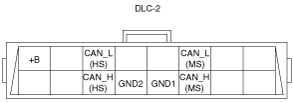
DLC-2 Outline
am3zzn00000547
|
|
Terminal name |
Function |
|---|---|
|
B+
|
Battery positive voltage
|
|
CAN_H (HS)
|
CAN communication line (HS)
|
|
CAN_L (HS)
|
CAN communication line (HS)
|
|
GND1
|
Ground (chassis)
|
|
GND2
|
Ground (signal)
|
|
CAN_H (MS)
|
CAN communication line (MS)
|
|
CAN_L (MS)
|
CAN communication line (MS)
|