 |
am3zzn00000547
ON-BOARD DIAGNOSTIC SYSTEM TEST MODE [MZ-CD 1.4 DI Turbo]
id0102c6100200
|
Diagnostic test mode |
Item |
|---|---|
|
Mode 01
|
Sending diagnostic data (PID data monitor/On-board system readiness test)
|
|
Mode 02
|
Sending freeze frame data
|
|
Mode 03
|
Sending emission-related malfunction code (DTC)
|
|
Mode 04
|
Clearing/resetting emission-related malfunction information
|
|
Mode 09
|
Request vehicle information
|
Sending Diagnostic Data
PID data monitor
PID/DATA monitor item table
|
Item |
Definition |
Unit/Condition |
|||
|---|---|---|---|---|---|
|
A/C_PRES
|
A/C pressure sensor
|
V
|
|||
|
Pa
|
Bar
|
psi
|
|||
|
AC_REQ
|
A/C request signal
|
Off/On
|
|||
|
ACCS
|
A/C compressor cycling switch
|
Off/On
|
|||
|
ALTF
|
Generator field current control duty signal
|
%
|
|||
|
APP1
|
APP sensor No.1
|
V
|
|||
|
%
|
|||||
|
APP2
|
APP sensor No.2
|
%
|
|||
|
ARPMDES
|
Desired RPM
|
RPM
|
|||
|
BARO
|
Barometric pressure
|
Pa
|
Bar
|
psi
|
|
|
BAT
|
Boost air temperature sensor
|
°C
|
°F
|
||
|
BAT_V
|
V
|
||||
|
BOO
|
Brake switch
|
Off/On
|
|||
|
BPA
|
Brake pressure applied switch
|
Off/On
|
|||
|
CPP
|
CPP Switch
|
Off/On
|
|||
|
ECT
|
Engine coolant temperature
|
V
|
|||
|
°C
|
°F
|
||||
|
EGRP
|
Exhaust gas recirculation valve position
|
V
|
|||
|
%
|
|||||
|
ENG_TORQ
|
Engine torque
|
N·m
|
|||
|
ETC_DSD
|
Electronic throttle control desired
|
%
|
|||
|
FAN1
|
FAN1 control signal
|
Off/On
|
|||
|
FAN2
|
FAN2 control signal
|
Off/On
|
|||
|
FLI
|
Fuel level
|
%
|
|||
|
FLT
|
Fuel temperature
|
°C
|
°F
|
||
|
FRP
|
Fuel rail pressure
|
V
|
|||
|
Pa
|
Bar
|
psi
|
|||
|
FUEL_PCV
|
Fuel pressure relief control valve
|
%
|
|||
|
A
|
|||||
|
FUEL_VCV
|
Fuel volume control valve
|
%
|
|||
|
GPC
|
Glow plug control
|
Off/On
|
|||
|
GPC_MON
|
Glow plug control relay monitor
|
Off/On
|
|||
|
IAT
|
Intake air temperature
|
V
|
|||
|
°C
|
°F
|
||||
|
INJ_1
|
Injector 1
|
Off/On
|
|||
|
INJ_2
|
Injector 2
|
Off/On
|
|||
|
INJ_3
|
Injector 3
|
Off/On
|
|||
|
INJ_4
|
Injector 4
|
Off/On
|
|||
|
INJ1_COR
|
Cylinder balancing offset injector 1
|
—
|
|||
|
INJ2_COR
|
Cylinder balancing offset injector 2
|
—
|
|||
|
INJ3_COR
|
Cylinder balancing offset injector 3
|
—
|
|||
|
INJ4_COR
|
Cylinder balancing offset injector 4
|
—
|
|||
|
IVS
|
Idle validation switch
|
Idle/Off Idle
|
|||
|
LOW_OIL
|
Engine oil level status
|
Yes/No
|
|||
|
MAF
|
Mass air flow
|
g/sec
|
|||
|
MAP
|
MAP sensor
|
Pa
|
Bar
|
psi
|
|
|
MIL_DIS
|
The distance travelled since the MIL was activated
|
Km
|
|||
|
RPM
|
Engine revolutions per minute
|
RPM
|
|||
|
SC_MODE
|
Cruise operation mode
|
NOT_ACT/KEEP_SPD/Accel/Decel/RES_HIGH/RES_LOW
|
|||
|
SEGRP DSD
|
Desired EGR valve position
|
%
|
|||
|
TP1
|
TP sensor 1
|
V
|
|||
|
VPWR
|
Module supply voltage
|
V
|
|||
|
VSS
|
Vehicle speed
|
KPH
|
|||
Sending Freeze Frame Data
Freeze frame data monitor table
|
Full names |
Unit |
|
|---|---|---|
|
DTC that caused the freeze frame
|
No unit
|
|
|
Calculated load value
|
%
|
|
|
Coolant temperature
|
°C
|
°F
|
|
Intake manifold pressure
|
kPa
|
|
|
Engine speed
|
rpm
|
|
|
Vehicle speed
|
km/h
|
mph
|
|
Intake air temperature
|
°C
|
°F
|
|
Air flow rate
|
g/s
|
|
|
TP sensor
|
%
|
|
|
Fuel rail pressure
|
kPa
|
|
Sending Emission-related Malfunction Code
|
DTC No. |
Condition |
MIL |
Powertrain warning light |
|---|---|---|---|
|
P0001
|
Fuel Volume Regulator Control Circuit/Open
|
—
|
ON
|
|
P0002:00
|
Fuel Volume Regulator Control Circuit Range/Performance
|
—
|
ON
|
|
P0003:00
|
Fuel Volume Regulator Control Circuit Low
|
—
|
ON
|
|
P0004:00
|
Fuel Volume Regulator Control Circuit High
|
—
|
ON
|
|
P0016:00
|
Crankshaft Position Sensor A Circuit Range/Performance
|
—
|
ON
|
|
P0069:00
|
MAP - Barometric Pressure Correlation
|
ON
|
—
|
|
P0088:00
|
Fuel Rail/System Pressure - Too High
|
—
|
ON
|
|
P0089:00
|
Fuel Rail/System Pressure - Too Low
|
—
|
ON
|
|
Fuel Pressure Regulator Performance
|
—
|
ON
|
|
|
P0090:00
|
Fuel Pressure Regulator Control Circuit
|
—
|
ON
|
|
P0091:00
|
Fuel Pressure Regulator Control Circuit Low
|
—
|
ON
|
|
P0092:00
|
Fuel Pressure Regulator Control Circuit High
|
—
|
ON
|
|
P0095
|
Intake Air Temperature Sensor 2 Circuit
|
ON
|
—
|
|
P0097:00
|
Intake Air Temperature Sensor 2 Circuit Low Input
|
ON
|
—
|
|
P0098:00
|
Intake Air Temperature Sensor 2 Circuit High Input
|
ON
|
—
|
|
P0099:00
|
Intake Air Temperature Sensor 2 Circuit Intermittent/Erratic
|
ON
|
—
|
|
P0100
|
Exhaust Gas Recirculation Control Circuit
|
ON
|
—
|
|
Mass or Volume Air Flow A Circuit
|
ON
|
—
|
|
|
P0101:00
|
Exhaust Gas Recirculation Control Circuit
|
ON
|
—
|
|
Mass or Volume Air Flow A Circuit Range/Performance
|
ON
|
—
|
|
|
P0102:00
|
Exhaust Gas Recirculation Control Circuit Range/Performance
|
ON
|
—
|
|
P0103:00
|
Exhaust Gas Recirculation Control Circuit Range/Performance
|
ON
|
—
|
|
P0105
|
Manifold Absolute Pressure/BARO Circuit
|
ON
|
—
|
|
P0106:00
|
Manifold Abs Press/BARO Sensor Range/Perform
|
—
|
—
|
|
P0107:00
|
Manifold Absolute Pressure/BARO Sensor Low Input
|
ON
|
—
|
|
P0108:00
|
Manifold Absolute Pressure/BARO Sensor High Input
|
ON
|
—
|
|
P0109:00
|
Manifold Absolute Pressure/BARO Sensor Intermittent
|
—
|
—
|
|
P010F:00
|
Mass or Volume Air Flow Sensor A/B Correlation
|
ON
|
ON
|
|
P0110
|
Intake Air Temperature Sensor 1 Circuit
|
ON
|
—
|
|
P0112:00
|
Intake Air temperature sensor voltage min
|
ON
|
—
|
|
P0113:00
|
Intake Air temperature sensor voltage max
|
ON
|
—
|
|
P0114:00
|
Intake Air Temperature Sensor 1 Intermittent/Erratic
|
ON
|
—
|
|
P0115
|
Cylinder Head Temperature Sensor Out of Self Test Range
|
ON
|
—
|
|
P0117:00
|
Cylinder Head Temperature Sensor Circuit Low
|
ON
|
—
|
|
P0118:00
|
Cylinder Head Temperature Sensor Circuit High
|
ON
|
—
|
|
P0180
|
Fuel Temperature Sensor A Circuit
|
—
|
—
|
|
P0182:00
|
Fuel Temperature Sensor A Circuit Low Input
|
—
|
—
|
|
P0183:00
|
Fuel Temperature Sensor A Circuit High Input
|
—
|
—
|
|
P0184:00
|
Fuel Temperature Sensor A Circuit Intermittent
|
—
|
—
|
|
P0190
|
Fuel Rail Pressure Sensor A Circuit
|
—
|
ON
|
|
P0191:00
|
Fuel Rail Pressure Sensor A Circuit Range/Performance
|
—
|
ON
|
|
P0192:00
|
Fuel Rail Pressure Sensor A Circuit Low Input
|
—
|
ON
|
|
P0193:00
|
Fuel Rail Pressure Sensor A Circuit High Input
|
—
|
ON
|
|
P0194:00
|
Fuel Rail Pressure Sensor A Circuit Intermittent/Erratic
|
—
|
ON
|
|
P0200:00
|
Injector Circuit
|
—
|
ON
|
|
P0201:00
|
Injector Circuit/Open - Cylinder 1
|
—
|
ON
|
|
P0202:00
|
Injector Circuit/Open - Cylinder 2
|
—
|
ON
|
|
P0203:00
|
Injector Circuit/Open - Cylinder 3
|
—
|
ON
|
|
P0204:00
|
Injector Circuit/Open - Cylinder 4
|
—
|
ON
|
|
P0219:00
|
Engine Overspeed Condition
|
—
|
—
|
|
P0235
|
MAP-sensor signal gradient not plausible
|
ON
|
—
|
|
Turbo/Super Charger Boost Sensor A Circuit
|
ON
|
—
|
|
|
P0236:00
|
MAP-sensor signal gradient not plausible
|
ON
|
—
|
|
P0237:00
|
Turbo/Super Charger Boost Sensor A Circuit Low
|
ON
|
—
|
|
P0238:00
|
Turbo/Super Charger Boost Sensor A Circuit High
|
ON
|
—
|
|
P02CD:00
|
Cylinder 1 Fuel Injector Offset Learning at Max Limit
|
—
|
—
|
|
P02CF:00
|
Cylinder 2 Fuel Injector Offset Learning at Max Limit
|
—
|
—
|
|
P02D1:00
|
Cylinder 3 Fuel Injector Offset Learning at Max Limit
|
—
|
—
|
|
P02D3:00
|
Cylinder 4 Fuel Injector Offset Learning at Max Limit
|
—
|
—
|
|
P0335:38
|
Crankshaft Position Sensor A Circuit - signal frequency incorrect
|
—
|
ON
|
|
P0335:64
|
Crankshaft Position Sensor A Circuit - signal plausibility failure
|
—
|
ON
|
|
P0336
|
Crankshaft Position Sensor A Circuit Range/Performance
|
—
|
ON
|
|
P0336:29
|
Crankshaft Position Sensor A Circuit Range/Performance - signal invalid
|
—
|
ON
|
|
P0336:31
|
Crankshaft Position Sensor A Circuit Range/Performance- no signal
|
—
|
ON
|
|
P0341
|
Camshaft Position Sensor A Circuit Range/Performance (Bank 1 or single sensor)
|
—
|
ON
|
|
P0341:29
|
Camshaft Position Sensor A Circuit Range/Performance (Bank 1 or single sensor) - signal signal invalid
|
—
|
ON
|
|
P0341:31
|
Camshaft Position Sensor A Circuit Range/Performance (Bank 1 or single sensor) - no signal
|
—
|
ON
|
|
P0341:37
|
Camshaft Position Sensor A Circuit Range/Performance (Bank 1 or single sensor)- signal frequency too high
|
—
|
ON
|
|
P0341:38
|
Camshaft Position Sensor A Circuit Range/Performance (Bank 1 or single sensor) - signal frequency incorrect
|
—
|
ON
|
|
P0341:62
|
Camshaft Position Sensor A Circuit Range/Performance (Bank 1 or single sensor) - signal compare failure
|
—
|
ON
|
|
P0380:00
|
Glow Plug/Heater Circuit A
|
—
|
—
|
|
P0383:00
|
Glow Plug Control Module Control Circuit Low
|
—
|
—
|
|
P0384:00
|
Glow Plug Control Module Control Circuit High
|
—
|
—
|
|
P0403:00
|
Exhaust Gas Recirculation Control Circuit
|
ON
|
—
|
|
P0404
|
EGR Vacuum Regulator Solenoid Circuit
|
ON
|
—
|
|
P0405:00
|
Exhaust Gas Recirculation Sensor A Circuit Low
|
ON
|
—
|
|
P0406:00
|
Exhaust Gas Recirculation Sensor A Circuit High
|
ON
|
—
|
|
P0480
|
Fan 1 Control Circuit
|
—
|
—
|
|
P0481
|
Fan 2 Control Circuit
|
—
|
—
|
|
P0485:00
|
Control Module Unused Fault Code
|
—
|
—
|
|
P0489:00
|
Exhaust Gas Recirculation Control Circuit Low
|
ON
|
—
|
|
P0490:00
|
Exhaust Gas Recirculation Control Circuit High
|
ON
|
—
|
|
P0500:00
|
Vehicle Speed CAN Signal - Signal not plausible
|
ON
|
—
|
|
P0501:00
|
Vehicle Speed CAN Signal - signal plausibility failure
|
ON
|
—
|
|
P0504:00
|
Plausibility error between BLS and BTS
|
—
|
ON
|
|
P0513:00
|
Immobilizer ID Does Not Match
|
—
|
—
|
|
P0560
|
System Voltage
|
—
|
—
|
|
P0562:00
|
System Voltage Low
|
—
|
—
|
|
P0563:00
|
System Voltage High
|
—
|
—
|
|
P0578:00
|
Cruise Control Multi-Function Input A Circuit Stuck
|
—
|
—
|
|
P0604:00
|
Internal Control Module RAM Error
|
—
|
ON
|
|
P0605:00
|
Internal Control Module ROM Error
|
—
|
ON
|
|
P0606:00
|
ECM/PCM Processor
|
—
|
—
|
|
P0606:49
|
ECM/PCM Processor - internal electronic failure
|
—
|
ON
|
|
P060A
|
Internal Control Module Monitoring Processor Performance
|
—
|
ON
|
|
P060B:00
|
Internal Control Module A/D Processing Performance
|
—
|
—
|
|
P060C:00
|
Internal Control Module Main Processor Performance
|
—
|
ON
|
|
P060D:00
|
Internal Control Module Acc Pedal Position Performance
|
—
|
ON
|
|
P0615:00
|
Starter Relay Circuit
|
—
|
—
|
|
P0617:00
|
Starter Relay Circuit High
|
—
|
—
|
|
P061A:00
|
Internal Control Module Torque Performance
|
—
|
ON
|
|
P061B:00
|
Internal Control Module Torque Calculation Performance
|
—
|
ON
|
|
P061C:00
|
Internal Control Module Engine RPM Performance
|
—
|
ON
|
|
P061E:00
|
Internal Control Module Brake Signal Performance
|
—
|
ON
|
|
P062B:00
|
Internal Control Module Fuel Injector Control Performance
|
—
|
ON
|
|
P0641
|
Sensor Reference Voltage A Circuit/Open
|
—
|
ON
|
|
P0642:00
|
Sensor Reference Voltage A Circuit Low
|
—
|
ON
|
|
P0643:00
|
Sensor Reference Voltage A Circuit High
|
—
|
ON
|
|
P0645:00
|
A/C Clutch Relay Control Circuit
|
—
|
—
|
|
P0646:00
|
A/C Clutch Relay Control Circuit Low
|
—
|
—
|
|
P0647:00
|
A/C Clutch Relay Control Circuit High
|
—
|
—
|
|
P0651
|
Sensor Reference Voltage B Circuit/Open
|
—
|
ON
|
|
P0652:00
|
Sensor Reference Voltage B Circuit Low
|
—
|
ON
|
|
P0653:00
|
Sensor Reference Voltage B Circuit High
|
—
|
ON
|
|
P0670:00
|
Glow Plug Control Module Control Circuit/Open
|
—
|
—
|
|
P0691:00
|
Fan 1 Control Circuit Low
|
—
|
—
|
|
P0692:00
|
Fan 1 Control Circuit High
|
—
|
—
|
|
P0693:00
|
Fan 2 Control Circuit Low
|
—
|
—
|
|
P0694:00
|
Fan 2 Control Circuit High
|
—
|
—
|
|
P0704:00
|
Clutch Switch Input Circuit
|
—
|
—
|
|
P0A09:00
|
DC/DC Converter Status Circuit Low
|
ON
|
—
|
|
P0A10:00
|
DC/DC Converter Status Circuit High
|
ON
|
—
|
|
P0A94
|
DC/DC Converter Performance
|
ON
|
—
|
|
P115A:00
|
Low Fuel Level - Forced Limited Power
|
—
|
—
|
|
P115B:00
|
Low Fuel Level - Forced Engine Shutdown
|
—
|
—
|
|
P1201:00
|
Cylinder #1 Injector Circuit Open/Shorted
|
—
|
ON
|
|
P1202:00
|
Cylinder #2 Injector Circuit Open/Shorted
|
—
|
ON
|
|
P1203:00
|
Cylinder #3 Injector Circuit Open/Shorted
|
—
|
ON
|
|
P1204:00
|
Cylinder #4 Injector Circuit Open/Shorted
|
—
|
ON
|
|
P120F:00
|
Fuel Pressure Regulator Excessive Variation
|
—
|
ON
|
|
P1260
|
Theft Detected, Vehicle Immobilized
|
—
|
—
|
|
P1269:00
|
Immobilizer to PCM Signal Error
|
—
|
—
|
|
P1335:00
|
EGR Position Sensor Minimum/Maximum Stop Performance
|
ON
|
—
|
|
P141A:00
|
Exhaust Gas Recirculation Sensor A Circuit Intermittent/Erratic
|
ON
|
—
|
|
P1461:00
|
A/C pressure sensor circuit high
|
—
|
—
|
|
P1462:00
|
A/C pressure sensor circuit low
|
—
|
—
|
|
P1463:00
|
A/C pressure sensor insufficient Charge
|
—
|
—
|
|
P1510
|
Idle Signal Circuit
|
—
|
—
|
|
P151B:00
|
Idle Speed Control - RPM Lower Than Expected
|
—
|
—
|
|
P151C:00
|
Idle Speed Control - RPM Higher Than Expected
|
—
|
—
|
|
P1551:00
|
Injector Circuit Range/Performance - Cylinder 1
|
ON
|
ON
|
|
P1552:00
|
Injector Circuit Range/Performance - Cylinder 2
|
ON
|
ON
|
|
P1553:00
|
Injector Circuit Range/Performance - Cylinder 3
|
ON
|
ON
|
|
P1554:00
|
Injector Circuit Range/Performance - Cylinder 4
|
ON
|
ON
|
|
P1563:00
|
ECM/PCM Processor
|
ON
|
ON
|
|
P1602:00
|
Immobilizer Code Words Do Not Match
|
—
|
—
|
|
P1622:00
|
Immobilizer/ECM Communication Error
|
—
|
—
|
|
P1632
|
Smart Alternator Faults Sensor/Circuit
|
—
|
—
|
|
P1632:92
|
Smart Alternator Faults Sensor/Circuit - performance or incorrect operation
|
—
|
—
|
|
P1632:94
|
Smart Alternator Faults Sensor/Circuit - unexpected operation
|
—
|
—
|
|
P1632:98
|
Smart Alternator Faults Sensor/Circuit - over temperature
|
—
|
—
|
|
P1656:00
|
CAN Link PCM/PCM Circuit/Network
|
—
|
—
|
|
P1935:00
|
Brake Switch Sensor/Signal
|
—
|
ON
|
|
P1936:00
|
Clutch Switch/Sensor Signal
|
—
|
—
|
|
P193A:00
|
Invalid Scan Tool Communication/Request
|
—
|
ON
|
|
P193B:00
|
Throttle/Pedal Position Sensor/Switch B Circuit
|
—
|
—
|
|
P2120
|
Throttle/Pedal Position Sensor A Circuit
|
—
|
ON
|
|
P2122:00
|
Throttle/Pedal Position Sensor A Circuit Low Input -signal frequency too low
|
—
|
ON
|
|
P2122:32
|
Throttle/Pedal Position Sensor A Circuit Low Input - signal low time < minimum
|
—
|
ON
|
|
P2122:36
|
Throttle/Pedal Position Sensor A Circuit Low Input -signal frequency too low
|
—
|
ON
|
|
P2123:35
|
Throttle/Pedal Position Sensor A Circuit High Input - signal high time > maximum
|
—
|
ON
|
|
P2123:37
|
Throttle/Pedal Position Sensor A Circuit High Input - signal frequency too high
|
—
|
ON
|
|
P2125
|
Throttle/Pedal Position Sensor/Switch B Circuit
|
—
|
ON
|
|
P2127:00
|
Throttle/Pedal Position Sensor/Switch B Circuit Low Input
|
—
|
ON
|
|
P2128:00
|
Throttle/Pedal Position Sensor/Switch B Circuit High Input
|
—
|
ON
|
|
P2138:00
|
Throttle/Pedal Position Sensor/Switch A/B Voltage Correlation
|
—
|
ON
|
|
P2138:62
|
Throttle/Pedal Position Sensor/Switch A/B Voltage Correlation - signal compare failure
|
—
|
ON
|
|
P2299:00
|
Brake Pedal Position/Accelerator Pedal Position Incompatible
|
—
|
ON
|
|
P2505:00
|
ECM/PCM Power Input Signal
|
—
|
ON
|
|
P2506
|
ECM/PCM Power Input Signal Range/Performance
|
—
|
ON
|
|
P2507:00
|
ECM/PCM Power Input Signal Low
|
—
|
ON
|
|
P2508:00
|
ECM/PCM Power Input Signal High
|
—
|
ON
|
|
U0073:00
|
High Speed CAN Communication Bus
|
ON
|
—
|
|
U0121:00
|
Lost Communication With Anti-Lock Brake System (ABS) Control Module
|
ON
|
—
|
|
U0140:00
|
Lost Communication With Body Control Module
|
—
|
—
|
|
U0155
|
Lost Communication With Instrument Panel Cluster (IPC) Control Module
|
ON
|
—
|
|
U0416
|
Lost Communication With Power Steering Control Module
|
—
|
—
|
|
U0422:00
|
Invalid Data Received from Body Control Module
|
—
|
—
|
|
U0423
|
Invalid Data Received from Instrument Panel Control Module
|
ON
|
—
|
|
U1A04:00
|
Error on signal coming from CAN
|
ON
|
—
|
|
U2100:00
|
Control Module Configuration Incompatible
|
—
|
ON
|
|
U2101:00
|
Control Module Configuration Incompatible
|
—
|
ON
|
Sending Continuous Monitoring System Test Results
1-drive cycle type
2-drive cycle type
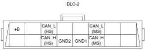
DLC-2 Outline
am3zzn00000547
|
|
Terminal name |
Function |
|---|---|
|
B+
|
Battery positive voltage
|
|
CAN_H (HS)
|
CAN communication line (HS)
|
|
CAN_L (HS)
|
CAN communication line (HS)
|
|
GND1
|
Ground (chassis)
|
|
GND2
|
Ground (signal)
|
|
CAN_H (MS)
|
CAN communication line (MS)
|
|
CAN_L (MS)
|
CAN communication line (MS)
|