 |
am2zzw00004047
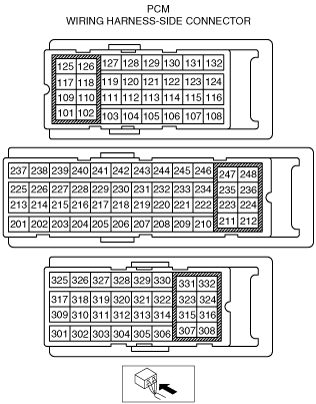
PCM INSPECTION [MZ-CD 1.6 (Y6)]
id0140b2802500
Not Using the M-MDS
am2zzw00004047
|
PCM terminal voltage table (Reference)
|
Terminal |
Signal name |
Connected to |
Measurement condition |
Voltage (V) |
Inspection item(s) |
|
|---|---|---|---|---|---|---|
|
101
|
Fuel injector No.1 (high)
|
Fuel injector No.1
|
Inspect using the wave Profile. (See Inspection Using An Oscilloscope (Reference).)
|
• Related wiring harness
• Fuel injector No.1
|
||
|
102
|
Fuel injector No.4 (high)
|
Fuel injector No.4
|
Inspect using the wave Profile. (See Inspection Using An Oscilloscope (Reference).)
|
• Related wiring harness
• Fuel injector No.4
|
||
|
103
|
Fuel temperature sensor Ground
|
Fuel temperature sensor
|
Under any condition
|
Below 1.0
|
• Related wiring harness
• Fuel temperature sensor
|
|
|
104
|
Variable boost control signal
|
Variable boost control solenoid valve
|
Inspect using the wave Profile. (See Inspection Using An Oscilloscope (Reference).)
|
• Related wiring harness
• Variable boost control solenoid valve
|
||
|
105
|
—
|
|||||
|
106
|
—
|
|||||
|
107
|
—
|
|||||
|
108
|
Starter
|
Starter relay
|
Cranking
|
Below 1.0
|
• Related wiring harness
• Starter relay
|
|
|
109
|
Fuel injector No.3 (high)
|
Fuel injector No.3
|
Inspect using the wave Profile. (See Inspection Using An Oscilloscope (Reference).)
|
• Related wiring harness
• Fuel injector No.3
|
||
|
110
|
Fuel injector No.2 (high)
|
Fuel injector No.2
|
Inspect using the wave Profile. (See Inspection Using An Oscilloscope (Reference).)
|
• Related wiring harness
• Fuel injector No.2
|
||
|
111
|
—
|
|||||
|
112
|
—
|
|||||
|
113
|
Catalyst exhaust gas temperature sensor No.1 ground
|
Catalyst exhaust gas temperature sensor No.1
|
Under any condition
|
1.0 or less
|
• Catalyst exhaust gas temperature sensor
• Related wiring harness
|
|
|
114
|
Catalyst exhaust gas temperature sensor No.2 ground
|
Catalyst exhaust gas temperature sensor No.2
|
Under any condition
|
1.0 or less
|
• Catalyst exhaust gas temperature sensor
• Related wiring harness
|
|
|
115
|
—
|
|||||
|
116
|
—
|
|||||
|
117
|
Fuel injector No.4 (low)
|
Fuel injector No.4
|
Inspect using the wave Profile. (See Inspection Using An Oscilloscope (Reference).)
|
• Related wiring harness
• Fuel injector No.4
|
||
|
118
|
Fuel injector No.1 (low)
|
Fuel injector No.1
|
Inspect using the wave Profile. (See Inspection Using An Oscilloscope (Reference).)
|
• Related wiring harness
• Fuel injector No.1
|
||
|
119
|
Diesel particulate filter differential pressure sensor ground
|
Diesel particulate filter differential pressure sensor
|
Under any condition
|
1.0 or less
|
• Related wiring harness
• Fuel injector No.2
|
|
|
120
|
—
|
|||||
|
121
|
EGR valve position sensor ground
|
EGR valve
|
Switch the ignition ON
|
Below 1.0
|
• Diesel particulate filter differential pressure sensor
• Related wiring harness
|
|
|
122
|
—
|
|||||
|
123
|
Glow plug relay monitor
|
Glow plug relay
|
Switch the ignition ON
|
Approx. 1.3
|
• Related wiring harness
• Glow plug relay
|
|
|
Idle after warm-up
|
B+
|
|||||
|
124
|
MAF
|
MAF/IAT sensor
|
Inspect using the wave Profile. (See Inspection Using An Oscilloscope (Reference).)
|
• Related wiring harness
• MAF/IAT sensor
|
||
|
125
|
Fuel injector No.3 (low)
|
Fuel injector No.3
|
Inspect using the wave Profile. (See Inspection Using An Oscilloscope (Reference).)
|
• Related wiring harness
• Fuel injector No.3
|
||
|
126
|
Fuel injector No.2 (low)
|
Fuel injector No.2
|
Inspect using the wave Profile. (See Inspection Using An Oscilloscope (Reference).)
|
• Related wiring harness
• Fuel injector No.2
|
||
|
127
|
—
|
|||||
|
128
|
—
|
|||||
|
129
|
EGR valve position
|
EGR valve
|
Idle
|
Approx. 2.9
|
• Related wiring harness
• EGR valve
|
|
|
Switch the ignition ON
|
Approx. 0.9
|
|||||
|
130
|
—
|
|||||
|
131
|
—
|
|||||
|
132
|
Throttle valve position sensor signal
|
Throttle valve position sensor
|
Switch the ignition ON
|
Approx. 3.1
|
• Throttle valve position sensor
• Related wiring harness
|
|
|
Idle
|
Approx. 3.4
|
|||||
|
201
|
EGR valve position sensor supply
|
EGR valve
|
Switch the ignition ON
|
Approx. 5.0
|
• Related wiring harness
• EGR valve
|
|
|
202
|
Fuel pressure sensor supply
|
Fuel pressure sensor
|
Switch the ignition ON
|
Approx. 5.0
|
• Related wiring harness
• Fuel pressure sensor
|
|
|
203
|
Fuel pressure sensor ground
|
Fuel pressure sensor
|
Switch the ignition ON
|
Below 1.0
|
• Related wiring harness
• Fuel pressure sensor
|
|
|
204
|
MAP sensor ground
|
MAP sensor
|
Switch the ignition ON
|
Below 1.0
|
• Related wiring harness
• MAP sensor
|
|
|
205
|
MAP sensor supply
|
MAP sensor
|
Switch the ignition ON
|
Approx. 5.0
|
• Related wiring harness
• MAP sensor
|
|
|
206
|
CMP sensor supply
|
CMP sensor
|
Switch the ignition ON
|
Approx. 5.0
|
• Related wiring harness
• CMP sensor
|
|
|
207
|
Diesel particulate filter differential pressure sensor supply
|
Diesel particulate filter differential pressure sensor
|
Switch the ignition ON
|
Approx. 5.0
|
• Diesel particulate filter differential pressure sensor
• Related wiring harness
|
|
|
208
|
—
|
|||||
|
209
|
—
|
|||||
|
210
|
—
|
|||||
|
211
|
IAT sensor No.2 ground
|
IAT sensor No.2
|
Under any condition
|
Below 1.0
|
• Related wiring harness
• IAT sensor No.2
|
|
|
212
|
Fuel metering valve control signal
|
Fuel metering valve
|
Inspect using the wave Profile. (See Inspection Using An Oscilloscope (Reference).)
|
• Fuel metering valve
• Related wiring harness
|
||
|
213
|
—
|
|||||
|
214
|
—
|
|||||
|
215
|
—
|
|||||
|
216
|
—
|
|||||
|
217
|
—
|
|||||
|
218
|
CKP sensor supply
|
CKP sensor
|
Switch the ignition ON
|
Approx. 5.0
|
• Related wiring harness
• CKP sensor
|
|
|
219
|
Fuel pressure
|
Fuel pressure sensor
|
Switch the ignition off
|
Below 1.0
|
• Related wiring harness
• Fuel pressure sensor
|
|
|
Switch the ignition ON
|
Approx. 5.0
|
|||||
|
220
|
Catalyst exhaust gas temperature sensor No.2 signal
|
Catalyst exhaust gas temperature sensor No.2
|
Inspect using the M-MDS
|
• Catalyst exhaust gas temperature sensor
• Related wiring harness
|
||
|
221
|
Catalyst exhaust gas temperature sensor No.1 signal
|
Catalyst exhaust gas temperature sensor No.1
|
Inspect using the M-MDS
|
• Catalyst exhaust gas temperature sensor
• Related wiring harness
|
||
|
222
|
—
|
|||||
|
223
|
—
|
|||||
|
224
|
—
|
|||||
|
225
|
—
|
|||||
|
226
|
Oil pressure
|
Oil pressure switch
|
Switch the ignition ON
|
Below 1.0
|
• Related wiring harness
• Oil pressure switch
|
|
|
Idle
|
B+
|
|||||
|
227
|
EGR valve actuator
|
EGR valve
|
Inspect using the wave Profile. (See Inspection Using An Oscilloscope (Reference).)
|
• Related wiring harness
• EGR valve
|
||
|
228
|
EGR valve actuator
|
EGR valve
|
Under any condition
|
Below 1.0
|
• Related wiring harness
• EGR valve
|
|
|
229
|
MAF sensor ground
|
MAF sensor
|
Under any condition
|
Below 1.0
|
• Related wiring harness
• MAF sensor
|
|
|
230
|
ECT
|
ECT sensor
|
Engine coolant temperature:30°C {86°F}
|
Approx. 2.6
|
• Related wiring harness
• ECT sensor
|
|
|
Engine coolant temperature:70°C {158°F}
|
Approx. 1.1
|
|||||
|
231
|
IAT
|
MAF/IAT sensor
|
Switch the ignition ON
|
IAT 30 °C {86 °F}
|
Approx. 2.1
|
• Related wiring harness
• MAF/IAT sensor
|
|
IAT 60 °C {140 °F}
|
Approx. 1.1
|
|||||
|
232
|
Fuel temperature
|
Fuel temperature sensor
|
Fuel temperature:43°C {109.4°F}
|
Approx. 1.6
|
• Related wiring harness
• Fuel temperature sensor
|
|
|
Fuel temperature:47°C {116.6°F}
|
Approx. 1.3
|
|||||
|
233
|
—
|
|||||
|
234
|
MAP
|
MAP sensor
|
Switch the ignition ON
|
Approx. 2.4
|
• Related wiring harness
• MAP sensor
|
|
|
235
|
—
|
|||||
|
236
|
Power supply
|
Main relay
|
Switch the ignition ON
|
B+
|
• Related wiring harness
• Main relay
|
|
|
237
|
CMP sensor ground
|
CMP sensor
|
Under any condition
|
Below 1.0
|
• Related wiring harness
• CMP sensor
|
|
|
238
|
CKP
|
CKP sensor
|
Inspect using the wave Profile. (See Inspection Using An Oscilloscope (Reference).)
|
• Related wiring harness
• CKP sensor
|
||
|
239
|
CKP sensor ground
|
CKP sensor
|
Switch the ignition ON
|
Below 1.0
|
• Related wiring harness
• CKP sensor
|
|
|
240
|
CMP
|
CMP sensor
|
Inspect using the wave Profile. (See Inspection Using An Oscilloscope (Reference).)
|
• Related wiring harness
• CMP sensor
|
||
|
241
|
Main relay control
|
Main relay
|
Switch the ignition ON
|
Approx. 0.9
|
• Related wiring harness
• Main relay
|
|
|
242
|
IAT
|
IAT sensor No.2
|
Switch the ignition ON
|
IAT 30 °C {86 °F}
|
Approx. 3.5
|
• Related wiring harness
• IAT sensor No.2
|
|
243
|
—
|
|||||
|
244
|
ECT sensor ground
|
ECT sensor
|
Under any condition
|
Below 1.0
|
• Related wiring harness
• ECT sensor
|
|
|
245
|
—
|
|||||
|
246
|
Diesel particulate filter differential pressure sensor signal
|
Diesel particulate filter differential pressure sensor
|
Inspect using the M-MDS
|
• Diesel particulate filter differential pressure sensor
• Related wiring harness
|
||
|
247
|
Throttle valve actuator control signal
|
Throttle valve actuator
|
Switch the ignition ON
|
Approx. 0.6
|
• Throttle valve position sensor
• Related wiring harness
|
|
|
248
|
—
|
|||||
|
301
|
CAN_H
|
Controller area network (high)
|
Because this terminal is for CAN, determination by terminal voltage is not possible.
|
• Related wiring harness
|
||
|
302
|
—
|
|||||
|
303
|
—
|
|||||
|
304
|
Cooling fan relay No.3
|
Cooling fan relay No.3
|
Cooling fan relay No.3 operating
|
Below 1.0
|
• Related wiring harness
• Cooling fan relay No.3
|
|
|
Cooling fan relay No.3 not operating
|
B+
|
|||||
|
305
|
—
|
|||||
|
306
|
Refrigerant pressure sensor ground
|
Refrigerant pressure sensor
|
Under any condition
|
Below 1.0
|
• Related wiring harness
• Refrigerant pressure sensor
|
|
|
307
|
Ground
|
Body ground
|
Under any condition
|
Below 1.0
|
• Related wiring harness
|
|
|
308
|
Ground
|
Body ground
|
Under any condition
|
Below 1.0
|
• Related wiring harness
|
|
|
309
|
CAN_L
|
Controller area network (low)
|
Because this terminal is for CAN, determination by terminal voltage is not possible.
|
• Related wiring harness
|
||
|
310
|
APP
|
APP sensor
|
Accelerator pedal released
|
Approx. 3.3
|
• Related wiring harness
• APP sensor
|
|
|
Accelerator pedal depressed
|
Approx. 8.0
|
|||||
|
311
|
Ignition switch
|
Ignition switch
|
Switch the ignition ON
|
B+
|
• Related wiring harness
• Ignition switch
|
|
|
312
|
—
|
|||||
|
313
|
—
|
|||||
|
314
|
—
|
|||||
|
315
|
—
|
|||||
|
316
|
—
|
|||||
|
317
|
Brake
|
Brake switch
|
Brake pedal released
|
Below 1.0
|
• Related wiring harness
• Brake switch
|
|
|
Brake pedal depressed
|
B+
|
|||||
|
318
|
Cooling fan relay No.1
|
Cooling fan relay No.1
|
Cooling fan relay No.1 operating
|
Below 1.0
|
• Related wiring harness
• Cooling fan relay No.1
|
|
|
Cooling fan relay No.1 not operating
|
B+
|
|||||
|
319
|
—
|
|||||
|
320
|
Generator
|
Generator
|
Under any condition
|
Below 1.0
|
• Related wiring harness
• Generator
|
|
|
321
|
—
|
|||||
|
322
|
—
|
|||||
|
323
|
Refrigerant pressure sensor supply
|
Refrigerant pressure sensor
|
Switch the ignition ON
|
Approx. 5.0
|
• Related wiring harness
• Refrigerant pressure sensor
|
|
|
324
|
Refrigerant pressure
|
Refrigerant pressure sensor
|
Switch the ignition ON
|
Approx. 1.5
|
• Related wiring harness
• Refrigerant pressure sensor
|
|
|
325
|
—
|
|||||
|
326
|
Glow plug relay
|
Glow plug relay
|
Glow plug relay operating
|
Below 1.0
|
• Related wiring harness
• Glow plug relay
|
|
|
Glow plug relay not operating
|
B+
|
|||||
|
327
|
—
|
|||||
|
328
|
—
|
|||||
|
329
|
—
|
|||||
|
330
|
A/C relay
|
A/C relay
|
Idle
|
Refrigerant pressure switch on
|
Below 1.0
|
• Related wiring harness
• A/C relay
|
|
Refrigerant pressure switch off
|
B+
|
|||||
|
331
|
Power supply
|
Main relay
|
Switch the ignition ON
|
B+
|
• Related wiring harness
• Main relay
|
|
|
332
|
Ground
|
Body ground
|
Under any condition
|
Below 1.0
|
• Related wiring harness
|
|
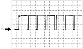
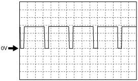
Inspection Using An Oscilloscope (Reference)
Fuel injector (+) signal
am2zzw00003096
|
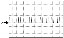
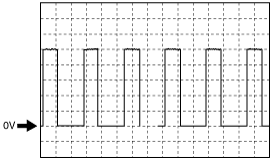
Variable boost control signal
am2zzw00004052
|
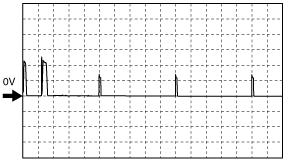
Fuel injector (-) signal
am2zzw00003097
|
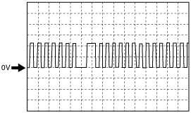
MAF sensor signal
am2zzw00004051
|
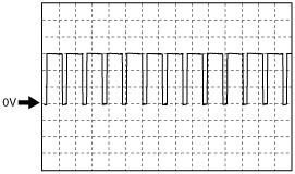
Fuel metering valve signal
am2zzw00004053
|
EGR valve actuator signal
am2zzw00002952
|
CKP sensor signal
am2zzw00002951
|
CMP sensor signal
am2zzw00002954
|
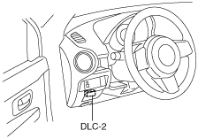
Using the M-MDS
1. Connect the M-MDS to the DLC-2.
am2zzw00004008
|
2. Turn the ignition switch to the ON position.
3. Measure the PID value.
PID monitor table (reference)
|
Item (Definition) |
Unit/ Condition |
Condition/Specification (Reference) |
Inspection item(s) |
|
|---|---|---|---|---|
|
AAT
(Ambient air temperature)
|
°C
|
Indicates the ambient air temperature
|
—
|
|
|
AC_PRES
(A/C pressure sensor)
|
Pa
|
Idle
|
A/C switch ON: Approx. 1.15 MPa
A/C switch OFF: Approx. 807 kPa
|
• A/C pressure sensor
|
|
V
|
A/C switch ON: Approx. 1.83 V
A/C switch OFF: Approx.1.43 V
|
|||
|
ACCS
(Air conditioning compressor cycling switch)
|
Off/On
|
Idle A/C switch ON: On
Idle A/C switch OFF: Off
|
• The following PIDs
|
|
|
APP
(Accelerator pedal position)
|
%
|
Switch the ignition ON
|
Accelerator pedal released: 0 %
Accelerator pedal depressed: 100 %
|
• APP sensor
|
|
APP1
(Accelerator pedal position No.1)
|
%
|
Switch the ignition ON
|
Accelerator pedal released: 7.84 %
Accelerator pedal depressed: 65.88 %
|
• APP sensor
|
|
APP2
(Accelerator pedal position No.2)
|
%
|
Switch the ignition ON
|
Accelerator pedal released: 7.45 %
Accelerator pedal depressed: 67.05 %
|
• APP sensor
|
|
BARO
(Barometric pressure)
|
Pa
|
Indicates the barometric pressure.
|
—
|
|
|
BAT
(Boost air temperature sensor)
|
V
|
BAT 40 °C {104 °F}: Approx. 2.7 V
BAT 45 °C {113 °F}: Approx. 2.5 V
BAT 60 °C {140 °F}: Approx. 1.8 V
|
• IAT sensor No.2
|
|
|
°C
|
Indicates the intake air temperature.
|
|||
|
CATT11_DSD
(Desired catalyst temperature (Catalyst exhaust gas temperature sensor No.1))
|
°C
|
Indicates the target/estimated exhaust gas temperature (Catalyst exhaust gas temperature sensor No.1).
|
• Catalyst exhaust gas temperature sensor No.1
|
|
|
CATT12_DSD
(Desired catalyst temperature (Catalyst exhaust gas temperature sensor No.2))
|
°C
|
Indicates the target/estimated exhaust gas temperature (Catalyst exhaust gas temperature sensor No.2).
|
• Catalyst exhaust gas temperature sensor No.2
|
|
|
DPF_SM
(Soot mass In particle filter)
|
g
|
Indicates the soot quantity in the diesel particulate filter.
|
• Diesel particulate filter differential pressure sensor
|
|
|
DPF_SSM
(Simulated soot mass in particulate filter)
|
g
|
Indicates the estimated soot quantity in the diesel particulate filter.
|
—
|
|
|
DPF_USM
(Uncorrected soot mass of physical model)
|
g
|
Indicates the non-correction soot quantity of the theoretical model.
|
—
|
|
|
ECT
(Engine coolant temperature)
|
V
|
ECT 30 °C {86 °F}: Approx. 2.6 V
ECT 50 °C {122 °F}: Approx. 1.7 V
ECT 60 °C {140 °F}: Approx. 1.4 V
ECT 80 °C {176 °F}: Approx. 0.8 V
|
• ECT sensor
|
|
|
°C
|
Indicates the engine coolant temperature.
|
|||
|
EGRP
(Exhaust gas recirculation valve position)
|
V
|
Idle: Approx. 3.0 V
Switch the ignition ON: Approx. 2.58 V
|
• EGR valve
|
|
|
ENG_STAT
(Engine status)
|
Ready/Running/AFTERRUN
|
Idle: Running
Switch the ignition ON: Ready
Other: AFTERRUN
|
—
|
|
|
ETC_DSD
(Electronic throttle control desired)
|
%
|
Under any condition: 100 %
|
• Throttle position sensor
|
|
|
EXHPRESS_DIF
(Exhaust gas differential pressure)
|
V
|
Under any condition: 0.5 V
|
• Diesel particulate filter differential pressure sensor
|
|
|
Pa
|
Indicates the difference in exhaust gas pressure before and after passing the diesel particulate filter.
|
|||
|
FAN_DUTY
(Variable fan duty cycle)
|
%
|
Elapsed time period after A/C switched ON 100%
Elapsed time period after A/C switched off 0%
|
• Fun control module
|
|
|
FLT
(Fuel temperature)
|
V
|
FLT 25 °C: Approx. 2.43 V
FLT 38 °C: Approx. 1.74 V
|
• Fuel temperature sensor
|
|
|
°C
|
Indicates the fuel temperature.
|
|||
|
FRP
(Fuel rail pressure)
|
V
|
Idle: Approx. 0.99 V
Switch the ignition ON: Approx. 0.49 V
|
• Fuel pressure sensor
|
|
|
Pa
|
Idle: Approx. 22 MPa
Switch the ignition ON: Approx. 0 MPa
|
|||
|
FUEL_PCV
(Fuel pressure relief control valve)
|
%
|
Fuel pressure relief control valve is operated: 13 %
Fuel pressure relief control valve is not operated: 0 %
|
• Fuel pressure regulator
|
|
|
FUEL_VCV
(Fuel volume control valve)
|
%
|
Idle: Approx. 18.43 %
Switch the ignition ON: Approx. 13.72 %
|
• Fuel metering valve
|
|
|
GPC
(Glow plug control)
|
Off/On
|
Glow plug relay operating: On
Glow plug relay not operating: Off
|
• Glow plug relay
|
|
|
GPC_MON
(Glow plug control relay monitor)
|
Off/On
|
Glow plug relay operating: On
Glow plug relay not operating: Off
|
• Glow plug relay
|
|
|
IAT
(Intake air temperature)
|
V
|
IAT 29 °C {84 °F}: Approx. 2.2 V
IAT 33 °C {91 °F}: Approx. 1.8 V
IAT 44 °C {111 °F}: Approx. 1.5 V
|
• IAT sensor
|
|
|
°C
|
Indicates the intake air temperature.
|
|||
|
IMRC
(Intake manifold runner control)
|
%
|
This procedure is not for diagnosis
|
—
|
|
|
LOAD
(Engine load)
|
%
|
Idle: Approx. 19 %
Switch the ignition ON: 0 %
|
—
|
|
|
MAF
(Mass air flow)
|
g/sec
|
Idle: 10 g/sec
|
• MAF sensor
|
|
|
MAP
(Manifold absolute pressure sensor)
|
V
|
MAP 100 kPa: Approx. 2.37 V
|
• MAP sensor
|
|
|
Pa
|
Indicates the manifold absolute pressure.
|
|||
|
MIL_DIS
(The distance travelled since the MIL was activated.)
|
Km
|
Indicates the travelled distance since the MIL illuminated.
|
—
|
|
|
OIL_LEVEL
(Engine oil level)
|
%
|
Indicates the engine oil level.
|
—
|
|
|
OIL_TEMP
(Engine oil temperature)
|
V
|
OIL_TEMP 61 °C: 1.19 V
OIL_TEMP 34 °C: 0.75 V
|
—
|
|
|
°C
|
Indicates the engine oil temperature.
|
|||
|
REG_DEM
(Number of demanded regenerations of the particulate filter)
|
—
|
Indicates the required reproduction amount of the diesel particulate filter.
|
—
|
|
|
REG_SUC
(Number of successful regenerations of the particulate filter)
|
—
|
Indicates the actual reproduction amount of the diesel particulate filter.
|
—
|
|
|
RPM
(Engine revolutions per minute)
|
RPM
|
Idle: Approx. 750 rpm
|
• CKP sensor
|
|
|
SEGRP DSD
(Desired (SEGRP) valve position)
|
%
|
Indicates the desired EGR valve position.
|
• EGR valve
|
|
|
TOTAL_FUEL
(Total fuel quantity consumed since last filter cleaning)
|
L
|
Indicates the total fuel consumption amount after cleaning the filter.
|
• Fuel gauge sender unit
|
|
|
VBCV
(Variable boost control solenoid)
|
%
|
Idle: Approx. 17.72 %
2,000 rpm: Approx. 70.59 %
Switch the ignition ON: 12.45 %
|
• VBC solenoid valve
|
|
|
VBCV_DSD
(Desired variable boost control solenoid)
|
%
|
Idle: Approx. 21.0 %
Switch the ignition ON: Approx. 10.98 %
|
• VBC solenoid valve
|
|
|
VPWR
(Module supply voltage)
|
V
|
Switch the ignition ON: B+
|
• Battery
• Main relay
|
|
|
VSS
(Vehicle speed)
|
KPH
|
Indicates the vehicle speed.
|
• Wheel-speed sensor
|
|