am2zzn00001403
|
MALFUNCTION DETECTION FUNCTION [FN4A-EL]
id050218100300
Malfunction Detection Function
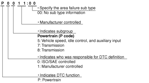
DTC 7-digit Code Definition
am2zzn00001403
|
DTC Table
|
DTC No. |
Condition |
MIL |
HOLD indicator light |
DC |
Monitor item |
Memory function |
|---|---|---|---|---|---|---|
|
P0706:00
|
TR switch circuit range/performance
|
ON
|
Flash
|
2
|
CCM
|
X
|
|
P0707:00
|
TR switch circuit low input
|
ON
|
Flash
|
1
|
CCM
|
X
|
|
P0708:00
|
TR switch circuit high input
|
ON
|
Flash
|
1
|
CCM
|
X
|
|
P0711:00
|
TFT sensor circuit range/performance
|
ON
|
OFF
|
2
|
CCM
|
X
|
|
P0712:00
|
TFT sensor circuit low input
|
ON
|
Flash
|
1
|
CCM
|
X
|
|
P0713:00
|
TFT sensor circuit high input
|
ON
|
Flash
|
1
|
CCM
|
X
|
|
P0715:00
|
Input/turbine speed sensor circuit malfunction
|
ON
|
Flash
|
1
|
CCM
|
X
|
|
P0720:00
|
VSS circuit malfunction
|
ON
|
Flash
|
2
|
CCM
|
X
|
|
P0731:00
|
Gear 1 incorrect ratio
|
OFF
|
Flash
|
1
|
CCM
|
X
|
|
P0732:00
|
Gear 2 incorrect ratio
|
OFF
|
Flash
|
1
|
CCM
|
X
|
|
P0733:00
|
Gear 3 incorrect ratio
|
OFF
|
Flash
|
1
|
CCM
|
X
|
|
P0734:00
|
Gear 4 incorrect ratio
|
OFF
|
Flash
|
1
|
CCM
|
X
|
|
P0741:00
|
TCC stuck off
|
OFF
|
Flash
|
1
|
CCM
|
X
|
|
P0742:00
|
TCC stuck on
|
OFF
|
Flash
|
1
|
CCM
|
X
|
|
P0745:00
|
Pressure control solenoid malfunction
|
OFF
|
Flash
|
1
|
CCM
|
X
|
|
P0751:00
|
Shift solenoid A stuck off
|
ON
|
Flash
|
2
|
CCM
|
X
|
|
P0752:00
|
Shift solenoid A stuck on
|
ON
|
Flash
|
2
|
CCM
|
X
|
|
P0753:00
|
Shift solenoid A electrical malfunction
|
ON
|
Flash
|
1
|
CCM
|
X
|
|
P0756:00
|
Shift solenoid B stuck off
|
ON
|
Flash
|
2
|
CCM
|
X
|
|
P0757:00
|
Shift solenoid B stuck on
|
ON
|
Flash
|
2
|
CCM
|
X
|
|
P0758:00
|
Shift solenoid B electrical malfunction
|
ON
|
Flash
|
1
|
CCM
|
X
|
|
P0761:00
|
Shift solenoid C stuck off
|
ON
|
Flash
|
2
|
CCM
|
X
|
|
P0762:00
|
Shift solenoid C stuck on
|
ON
|
Flash
|
2
|
CCM
|
X
|
|
P0763:00
|
Shift solenoid C electrical malfunction
|
ON
|
Flash
|
1
|
CCM
|
X
|
|
P0766:00
|
Shift solenoid D stuck off
|
ON
|
Flash
|
2
|
CCM
|
X
|
|
P0767:00
|
Shift solenoid D stuck on
|
OFF
|
Flash
|
2
|
CCM
|
X
|
|
P0768:00
|
Shift solenoid D electrical malfunction
|
ON
|
Flash
|
1
|
CCM
|
X
|
|
P0771:00
|
Shift solenoid E stuck off
|
ON
|
Flash
|
2
|
CCM
|
X
|
|
P0772:00
|
Shift solenoid E stuck on
|
ON
|
Flash
|
2
|
CCM
|
X
|
|
P0773:00
|
Shift solenoid E electrical malfunction
|
ON
|
Flash
|
1
|
CCM
|
X
|
|
P0883:00
|
TCM B+ high
|
ON
|
Flash
|
1
|
CCM
|
X
|
|
P0894:00
|
Transaxle component slipping
|
OFF
|
Flash
|
1
|
CCM
|
X
|
|
P1566:00
|
TCM B+ low
|
OFF
|
Flash
|
1
|
CCM
|
X
|
|
P1783:00
|
ATF high oil temperature malfunction
|
OFF
|
Flash
|
1
|
CCM
|
X
|
DTC Detection Condition
|
DTC No. |
On-board diagnostic function |
Detection condition |
|---|---|---|
|
P0706:00
|
TR switch circuit range/performance
|
• The PCM detects no position/range signal for 100 s when the following conditions are met.
|
|
P0707:00
|
TR switch circuit low input
|
• The PCM detects that input voltage from the TR switch is less than 0.49 V for 100 s when the following conditions are met.
|
|
P0708:00
|
TR switch circuit high input
|
• The PCM detects that input voltage from the TR switch is more than 4.78 V for 100 s when the following conditions are met.
|
|
P0711:00
|
TFT sensor circuit range/performance
|
• The PCM detects that input voltage from the TFT sensor is less than 0.03 V when the following conditions are met.
|
|
P0712:00
|
TFT sensor circuit low input
|
• The PCM detects that input voltage from the TFT sensor is less than 0.05 V for 150 s at vehicle speed 20 km/h {12 mph} or more.
|
|
P0713:00
|
TFT sensor circuit high input
|
• The PCM detects that input voltage from the TFT sensor is more than 4.66 V for 150 s at vehicle speed 20 km/h {12 mph} or more.
|
|
P0715:00
|
Input/turbine speed sensor circuit malfunction
|
• The PCM detects no signal from the input/turbine speed sensor at vehicle speed 41 km/h {25 mph} or more.
|
|
P0720:00
|
VSS circuit malfunction
|
• The PCM detects no signal from the VSS when the following conditions are met.
|
|
P0731:00
|
Gear 1 incorrect ratio
|
• The PCM detects that revolution ratio of the input revolution to output revolution is less than 2.185 four times when the following conditions are met.
|
|
P0732:00
|
Gear 2 incorrect ratio
|
• The PCM detects that revolution ratio of the input revolution to output revolution in 2GR is more than 2.185 or less than 1.277 three times.
|
|
P0733:00
|
Gear 3 incorrect ratio
|
• The PCM detects that revolution ratio of the input revolution to output revolution is between 1.404—1.704 when the following conditions are met.
• The PCM detects that revolution ratio of the input revolution to output revolution is less than 0.848 when the following conditions are met.
|
|
P0734:00
|
Gear 4 incorrect ratio
|
• The PCM detects that revolution ratio of the input revolution to output revolution is more than 1.277 or less than 0.57 when the following conditions are met.
• The PCM detects that revolution ratio of the input revolution to output revolution is between 0.91—1.09 when the following conditions are met.
|
|
P0741:00
|
TCC stuck off
|
• The PCM detects that difference between the engine revolution and turbine revolution is more than 100 rpm when the following conditions are met.
|
|
P0742:00
|
TCC stuck on
|
• The PCM detects that difference between the engine revolution and turbine revolution is less than 50 rpm when the following conditions are met.
|
|
P0745:00
|
Pressure control solenoid malfunction
|
• The PCM detects that output voltage to the pressure control solenoid is stuck at 0 V or B+ when the solenoid valve operates according to PCM calculation.
|
|
P0751:00
|
Shift solenoid A stuck off
|
• The PCM detects that revolution ratio of the input revolution to output revolution is between 0.91—1.09 when the following conditions are met.
|
|
P0752:00
|
Shift solenoid A stuck on
|
• The PCM detects that turbine revolution is more than 187.5 rpm with the vehicle stopped in D range.
|
|
P0753:00
|
Shift solenoid A electrical malfunction
|
• The PCM detects that output voltage to the shift solenoid A is stuck at 0 V or B+ when the solenoid valve operates according to PCM calculation.
|
|
P0756:00
|
Shift solenoid B stuck off
|
• The PCM detects that revolution ratio of the input revolution to output revolution is less than 2.185 four times when the following conditions are met.
|
|
P0757:00
|
Shift solenoid B stuck on
|
• The PCM detects that revolution ratio of the input revolution to output revolution in 2GR is more than 2.185 or less than 1.277 three times.
• The PCM detects that revolution ratio of the input revolution to output revolution is between 0.91—1.09 when the following conditions are met.
|
|
P0758:00
|
Shift solenoid B electrical malfunction
|
• The PCM detects that output voltage to the shift solenoid B is stuck at 0 V or B+ when the solenoid valve operates according to PCM calculation.
|
|
P0761:00
|
Shift solenoid C stuck off
|
• The PCM detects that revolution ratio of the input revolution to output revolution is less than 2.185 four times when the following conditions are met.
• The PCM detects that revolution ratio of the input revolution to output revolution in 2GR is more than 2.185 or less than 1.277 three times.
|
|
P0762:00
|
Shift solenoid C stuck on
|
• The PCM detects that revolution ratio of the input revolution to output revolution is between 1.404—1.704 when the following conditions are met.
|
|
P0763:00
|
Shift solenoid C electrical malfunction
|
• The PCM detects that output voltage to the shift solenoid C is stuck at 0 V or B+ when the solenoid valve operates according to PCM calculation.
|
|
P0766:00
|
Shift solenoid D stuck off
|
• The PCM detects that vehicle speed is more than 27 km/h {17 mph} when the following conditions are met.
|
|
P0767:00
|
Shift solenoid D stuck on
|
• The PCM detects that revolution ratio of the input revolution to output revolution is less than 0.848 when the following conditions are met.
|
|
P0768:00
|
Shift solenoid D electrical malfunction
|
• The PCM detects that output voltage to the shift solenoid D is stuck at 0 V or B+ when the solenoid valve operates according to PCM calculation.
|
|
P0771:00
|
Shift solenoid E stuck off
|
• The PCM detects that difference between the engine revolution and turbine revolution is more than 100 rpm when the following conditions are met.
|
|
P0772:00
|
Shift solenoid E stuck on
|
• The PCM detects that difference between the engine revolution and turbine revolution is less than 50 rpm when the following conditions are met.
|
|
P0773:00
|
Shift solenoid E electrical malfunction
|
• The PCM detects that output voltage to the shift solenoid E is stuck at 0 V or B+ when the solenoid valve operates according to PCM calculation.
|
|
P0883:00
|
TCM B+ high
|
• The PCM detects that battery voltage is more than 16.01 V.
|
|
P0894:00
|
Transaxle component slipping
|
• The PCM detects that turbine revolution is more than 187 rpm when the following conditions are met.
|
|
P1566:00
|
TCM B+ low
|
• The PCM detects that battery voltage is less than threshold (changes by ATF temperature) at engine speed 500 rpm or more.
|
|
P1783:00
|
ATF high oil temperature malfunction
|
• The PCM detects that ATF temperature is more than 149.5°C {301.1 °F} when the following conditions are met.
|
Fail-Safe Function
|
DTC No. |
On-board diagnostic function |
Fail-safe |
TCC |
|---|---|---|---|
|
P0706:00
|
TR switch circuit range/performance
|
• Inhibits 1GR and 4GR
• Inhibits feedback correction
|
Enabled
|
|
P0707:00
|
TR switch circuit low input
|
• Inhibits 1GR and 4GR
• Inhibits feedback correction
|
Enabled
|
|
P0708:00
|
TR switch circuit high input
|
• Inhibits 1GR and 4GR
• Inhibits feedback correction
|
Enabled
|
|
P0711:00
|
TFT sensor circuit range/performance
|
N/A
|
Disabled
|
|
P0712:00
|
TFT sensor circuit low input
|
• Switch the shift pattern to high temperature mode
• Inhibits feedback correction
|
Enabled
|
|
P0713:00
|
TFT sensor circuit high input
|
• Switch the shift pattern to high temperature mode
• Inhibits feedback correction
|
Enabled
|
|
P0715:00
|
Input/turbine speed sensor circuit malfunction
|
• Inhibits shifting to 4GR from 3GR
• Inhibits feedback correction
|
Disabled
|
|
P0720:00
|
VSS circuit malfunction
|
• Inhibits feedback correction
|
Enabled
|
|
P0731:00
|
Gear 1 incorrect ratio
|
• Inhibits 1GR
• Inhibits feedback correction
|
Enabled
|
|
P0732:00
|
Gear 2 incorrect ratio
|
• Inhibits 2GR
• Maximizes line pressure
• Inhibits feedback correction
|
Enabled
|
|
P0733:00
|
Gear 3 incorrect ratio
|
• Inhibits feedback correction
|
Enabled
|
|
P0734:00
|
Gear 4 incorrect ratio
|
• Inhibits 4GR
• Maximizes line pressure
• Inhibits feedback correction
|
Enabled
|
|
P0741:00
|
TCC stuck off
|
• Maximizes line pressure
• Inhibits feedback correction
|
Disabled
|
|
P0742:00
|
TCC stuck on
|
• Maximizes line pressure
• Inhibits feedback correction
|
Disabled
|
|
P0745:00
|
Pressure control solenoid malfunction
|
• Maximizes line pressure
• Inhibits feedback correction
|
Enabled
|
|
P0751:00
|
Shift solenoid A stuck off
|
• Inhibits 4GR
• Maximizes line pressure
• Inhibits feedback correction
|
Disabled
|
|
P0752:00
|
Shift solenoid A stuck on
|
• Inhibits 1GR, 2GR and 3GR
• Inhibits feedback correction
|
Enabled
|
|
P0753:00
|
Shift solenoid A electrical malfunction
|
• Inhibits 4GR
• Maximizes line pressure
• Inhibits feedback correction
|
Disabled
|
|
P0756:00
|
Shift solenoid B stuck off
|
• Inhibits 1GR and 4GR
• Inhibits shifting to 3GR from 2GR
• Inhibits shifting to 4GR from 3GR
• Maximizes line pressure
• Inhibits feedback correction
|
Enabled
|
|
P0757:00
|
Shift solenoid B stuck on
|
• Inhibits 2GR and 4GR
• Maximizes line pressure
• Inhibits feedback correction
|
Enabled
|
|
P0758:00
|
Shift solenoid B electrical malfunction
|
• Inhibits 1GR and 4GR
• Inhibits shifting to 3GR from 2GR
• Inhibits shifting to 4GR from 3GR
• Maximizes line pressure
• Inhibits feedback correction
|
Enabled
|
|
P0761:00
|
Shift solenoid C stuck off
|
• Inhibits 1GR and 2GR
• Maximizes line pressure
• Inhibits feedback correction
|
Enabled
|
|
P0762:00
|
Shift solenoid C stuck on
|
• Inhibits 3GR and 4GR
• Maximizes line pressure
• Inhibits feedback correction
|
Enabled
|
|
P0763:00
|
Shift solenoid C electrical malfunction
|
• Inhibits 1GR and 2GR
• Maximizes line pressure
• Inhibits feedback correction
|
Enabled
|
|
P0766:00
|
Shift solenoid D stuck off
|
• Inhibits 4GR
• Maximizes line pressure
• Inhibits feedback correction
|
Enabled
|
|
P0767:00
|
Shift solenoid D stuck on
|
• Inhibits 2GR and 4GR
• Maximizes line pressure
• Inhibits feedback correction
|
Disabled
|
|
P0768:00
|
Shift solenoid D electrical malfunction
|
• Inhibits 4GR
• Maximizes line pressure
• Inhibits feedback correction
|
Disabled
|
|
P0771:00
|
Shift solenoid E stuck off
|
• Maximizes line pressure
• Inhibits feedback correction
|
Disabled
|
|
P0772:00
|
Shift solenoid E stuck on
|
• Inhibits 1GR
• Maximizes line pressure
• Inhibits feedback correction
|
Disabled
|
|
P0773:00
|
Shift solenoid E electrical malfunction
|
• Maximizes line pressure
• Inhibits feedback correction
|
Disabled
|
|
P0883:00
|
TCM B+ high
|
• Inhibits 1GR, 2GR and 4GR
• Maximizes line pressure
|
Enabled
|
|
P0894:00
|
Transaxle component slipping
|
• Inhibits 1GR, 2GR and 3GR
• Maximizes line pressure
• Inhibits feedback correction
|
Enabled
|
|
P1566:00
|
TCM B+ low
|
• Inhibits 1GR, 2GR and 4GR
• Maximizes line pressure
|
Enabled
|
|
P1783:00
|
ATF high oil temperature malfunction
|
• Switch the shift pattern to high temperature mode
• Inhibits feedback correction
|
Enabled
|
KOEO/KOER Self-test
KOEO (Key ON, Engine Off) self-test
KOER (Key ON, Engine Running) self-test
Freeze Frame Data
Freeze frame data table
|
Freeze frame data item |
Unit |
Description |
Corresponding PID data monitor item |
|---|---|---|---|
|
FUELSYS1
|
Open Loop/Closed Loop/OL-Drive/OL-Fault/CL-Fault
|
Fuel system status
|
FUELSYS
|
|
LOAD
|
%
|
Calculated engine load
|
—
|
|
ECT
|
°C {°F}
|
Engine coolant temperature
|
ECT
|
|
SFT1
|
%
|
Short term fuel trim
|
SHRTFT1
|
|
LFT1
|
%
|
Long term fuel trim
|
LONGFT1
|
|
MAP
|
Pa {kgf/m2, psi}
|
Manifold absolute pressure
|
MAP
|
|
RPM
|
RPM
|
Engine speed
|
RPM
|
|
VS
|
KPH {MPH}
|
Vehicle speed
|
VSS
|
|
SPARKADV
|
°
|
Ignition timing
|
SPARKADV
|
|
IAT
|
°C {°F}
|
Intake air temperature
|
IAT
|
|
MAF
|
g/sec {lb/min}
|
Mass airflow
|
MAF
|
|
TP
|
%
|
Throttle valve position No.1
|
TP1
|
|
RUNTM
|
hh:mm:ss
|
Time from engine start
|
—
|
|
EGRPCT
|
%
|
Target EGR valve position
|
SEGRP_DSD
|
|
EVAPPCT
|
%
|
Purge solenoid valve controlled value
|
EVAPCP
|
|
WARMUPS
|
—
|
Number of warm-up cycle after DTC cleared
|
—
|
|
CLRDIST
|
Km {mile}
|
Mileage after DTC cleared
|
—
|
|
BARO
|
Pa {kgf/m2, psi}
|
Barometric pressure
|
—
|
|
CATTEMP11
|
°C {°F}
|
Estimated catalytic converter temperature
|
—
|
|
VPWR
|
V
|
Module supply voltage
|
VPWR
|
|
ALV
|
%
|
Engine load
|
LOAD
|
|
TP_REL
|
%
|
Relative throttle position
|
TP REL
|
|
TP_B
|
%
|
Throttle valve position No.2
|
TP2
|
|
APP_D
|
%
|
Accelerator pedal position No.1
|
APP1
|
|
APP_E
|
%
|
Accelerator pedal position No.2
|
APP2
|
|
TAC_PCT
|
%
|
Target throttle valve position
|
ETC_DSD
|
Snapshot data table
|
Snapshot data item |
Unit |
Definition |
Corresponding PID data monitor item |
|---|---|---|---|
|
FUELSYS
|
OL/CL/OL-Drive/OL-Fault/CL-Fault
|
Fuel system status
|
FUELSYS
|
|
LOAD_C
|
%
|
Calculated engine load
|
—
|
|
ECT
|
°C {°F}
|
Engine coolant temperature
|
ECT
|
|
SHRTFT1
|
%
|
Short term fuel trim
|
SHRTFT1
|
|
LONGFT1
|
%
|
Long term fuel trim
|
LONGFT1
|
|
MAP
|
Pa {kgf/m2, psi}
|
Manifold absolute pressure
|
MAP
|
|
RPM
|
RPM
|
Engine speed
|
RPM
|
|
VSS
|
KPH {MPH}
|
Vehicle speed
|
VSS
|
|
SPARKADV
|
°
|
Ignition timing
|
SPARKADV
|
|
IAT
|
°C {°F}
|
Intake air temperature
|
IAT
|
|
MAF
|
g/sec {lb/min}
|
Mass airflow
|
MAF
|
|
TP1
|
%
|
Throttle valve position No.1
|
TP1
|
|
EG_RUN_TIME
|
—
|
Time from engine start
|
—
|
|
SEGRP_DSD
|
%
|
Target EGR valve position
|
SEGRP DSD
|
|
EVAPCP
|
%
|
Purge solenoid valve controlled value
|
EVAPCP
|
|
FLI
|
%
|
Fuel level in fuel tank
|
—
|
|
CLR_CNT
|
—
|
Number of warm-up cycle after DTC cleared
|
—
|
|
CLR_DIST
|
Km {mile}
|
Mileage after DTC cleared
|
—
|
|
FTP
|
Pa {kgf/m2, psi}
|
Fuel tank pressure
|
—
|
|
BARO
|
Pa {kgf/m2, psi}
|
Barometric pressure
|
—
|
|
CATT11_DSD
|
°C {°F}
|
Estimated catalytic converter temperature
|
—
|
|
VPWR
|
V
|
Module supply voltage
|
VPWR
|
|
LOAD
|
%
|
Engine load
|
LOAD
|
|
EQ_RAT11_DSD
|
—
|
Target equivalence ratio (lambda)
|
EQ_RAT11_DSD
|
|
TP REL
|
%
|
Relative throttle position
|
TP REL
|
|
AAT
|
°C {°F}
|
Ambient air temperature
|
—
|
|
TP2
|
%
|
Throttle valve position No.2
|
TP2
|
|
APP1
|
%
|
Accelerator pedal position No.1
|
APP1
|
|
APP2
|
%
|
Accelerator pedal position No.2
|
APP2
|
|
ETC_DSD
|
%
|
Target throttle valve position
|
ETC_DSD
|