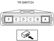
TRANSAXLE RANGE (TR) SWITCH INSTALLATION [FN4A-EL]


id051701803800

Caution
•  Water or foreign objects entering the connector can cause a poor connection or corrosion. Be sure not to drop water or foreign objects on the connector when disconnecting it.
•  Do not damage the terminals.

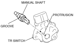
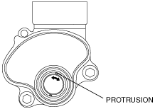
1.  Install the TR switch to the manual shaft.

(1)  Turn the protrusion between terminals B and C until the resistance becomes 713—787 ohms.
am2zzw00004860
am2zzw00004861
(2)  Install the TR switch while aligning the protrusion and groove as shown.
am2zzw00004862

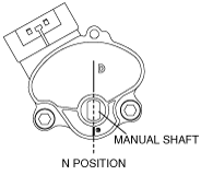
2.  Adjust the TR switch.

(1)  Verify that the TR switch is aligned with N position.
am2zzw00004863
(2)  Adjust the TR switch between terminals B and C until the resistance becomes specification.
am2zzw00004861
TR switch specification
713—787 ohms
(3)  Tighten the TR switch installation bolts.
Tightening torque
8—11 N·m {82—112 kgf·cm, 71—97 in·lbf}

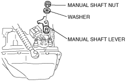
3.  Install the manual shaft lever and the washer.

am2zzw00004864

Caution
•  Do not use an impact wrench. Hold the manual shaft lever when removing the manual shaft nut, or the transaxle may be damaged.

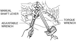
4.  Set the adjustable wrench as shown to hold the manual shaft lever, and tighten the manual shaft nut.

am2zzw00004867

Tightening torque
32—46 N·m {3.2—4.7 kgf·m, 24—33 ft·lbf}

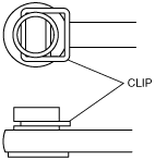
5.  Install the clip to the selector cable as shown in the figure.

am2zzw00004865

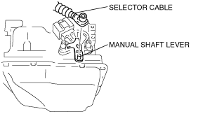
6.  Select the selector lever to N position.

7.  Connect the selector cable to the selector lever.

am2zzw00004866

8.  Connect the TR switch connector.

9.  Connect the negative battery cable.