 |
am3zzw00008501
TRANSAXLE RANGE (TR) SWITCH INSPECTION [DJVA-EL]
id051901285600
Operating Inspection
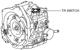
1. Perform the following procedures to inspect the TR switch.
On-Vehicle Inspection
1. Disconnect the negative battery cable.
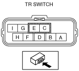
2. Disconnect the TR switch connector.
am3zzw00008501
|
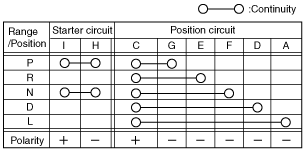
3. Inspect continuity as indicated in the table.
am2zzw00004302
|
am2zzw00004303
|
Wiring Harness Inspection
1. Remove the front side garnish. (See FRONT SIDE GARNISH REMOVAL/INSTALLATION.)
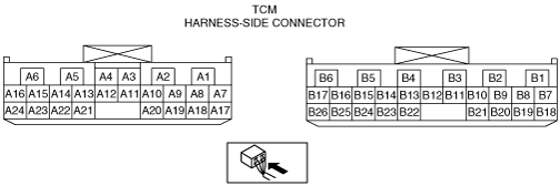
2. Disconnect the TCM connector.
3. Switch the ignition to ON.
4. Inspect for continuity between TR switch and TCM using a tester.
am3zzw00008444
|
TR switch specification
|
Terminal |
Specification (V) |
||||
|---|---|---|---|---|---|
|
P position |
R position |
N position |
D range |
L range |
|
|
B20—GND
|
VB
|
0V
|
0V
|
0V
|
0V
|
|
B1—GND
|
0V
|
VB
|
0V
|
0V
|
0V
|
|
B8—GND
|
0V
|
0V
|
VB
|
0V
|
0V
|
|
B7—GND
|
0V
|
0V
|
0V
|
VB
|
0V
|
|
B19—GND
|
0V
|
0V
|
0V
|
0V
|
VB
|