 |
am2zzw00005042
DTC B10D1:23 [ADVANCED KEYLESS AND START SYSTEM]
id0902e1388100
Detection Condition
Possible Causes
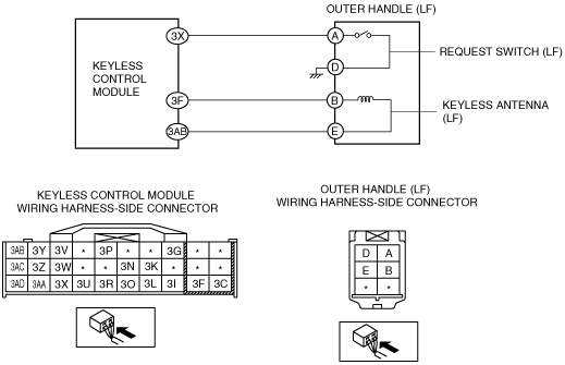
System Wiring Diagram
am2zzw00005042
|
Diagnostic Procedure
|
Step |
Inspection |
Action |
|
|---|---|---|---|
|
1
|
INSPECT OUTER HANDLE (LF) CONNECTOR
• Turn the ignition switch to the LOCK position.
• Disconnect the negative battery cable.
• Disconnect the outer handle (LF) connector.
• Inspect the outer handle (LF) connector. (Corrosion, damage, and disconnected pins)
• Are the connector and terminals normal?
|
Yes
|
Go to the next step.
|
|
No
|
Repair/replace the outer handle (LF) connector or terminal, then go to Step 5.
|
||
|
2
|
INSPECT KEYLESS CONTROL MODULE CONNECTOR
• Disconnect the keyless control module connector.
• Inspect the keyless control module connector. (Corrosion, damage, and disconnected pins)
• Are the connector and terminals normal?
|
Yes
|
Go to the next step.
|
|
No
|
Repair/replace the keyless control module connector or terminal, then go to Step 5.
|
||
|
3
|
INSPECT WIRING HARNESS BETWEEN OUTER HANDLE (LF) AND KEYLESS CONTROL MODULE FOR SHORT TO GROUND
• Outer handle (LF) and keyless control module connectors are disconnected.
• Inspect for continuity between outer handle (LF) terminal A (wiring harness-side) and body ground.
• Is there continuity?
|
Yes
|
Repair or replace the wiring harness between outer handle (LF) and keyless control module, then go to Step 5.
|
|
No
|
Go to the next step.
|
||
|
4
|
INSPECT REQUEST SWITCH (LF)
• Inspect the request switch (LF).
• Is the request switch (LF) normal?
|
Yes
|
Go to the next step.
|
|
No
|
Replace the request switch (LF), then go to the next step.
|
||
|
5
|
VERIFY DTCs
• Reconnect all disconnected connectors.
• Reconnect the negative battery cable.
• Clear the DTCs using the M-MDS.
• Verify the DTCs using the M-MDS.
• Is the DTC B10D1:23 displayed?
|
Yes
|
Replace the keyless control module.
|
|
No
|
DTC troubleshooting completed.
|
||